Senior Projects
Senior Projects:
-
"SDARS Front-End Receiver Integration", 2003.
-
"Antenna Array for Automotive Collision Avoidance", 2002.
-
"Distributed Amplifier Based Voltage Controlled Oscillator", 2002.
-
"SDARS Antenna and Receiver", 2001.
-
"An Active Duplexer for PCS", 2000.
-
"Detection and Synchronization in CDMA Receiver", 2000.
-
"900 MHz Wireless Link for Audio Applications", 2000.
-
"An Active Microstrip Antenna for GPS", 1998.
-
"A GaAs FET Mixer", 1998.
-
"A Wireless Communication Link for Audio Applications", 1998.
-
"A 24 GHz Proximity Sensor", 1997.
-
"A Compact 2.4 GHz Matched Variable Attenuator", 1997.
-
"A 2.4 GHz Matched Variable Attenuator", 1996.
-
"Linearizing Microwave Amplifier", 1996.
-
"A 2.4 GHz Transmit/Receive Module for Wireless Communications", 1995.
-
"A 2.4 GHz Wireless Communication Link", 1995.
-
"A 2.4 GHz Transceiver For Wireless Communications", 1994.
-
"A 2.4 GHz Electronic Tether: Digital Subsystem", 1994.
-
"A 2.4 GHz Electronic Tether: RF Subsystem", 1994.
-
"A 2.4 GHz Electronic Tether: Power Subsystem", 1994.
-
"A 4 GHz GaAs FET Power Amplifier", 1993.
-
"A 4 GHz GaAs FET Low Noise Amplifier", 1993.
-
"A Push-Pull Distributed Microwave Amplifier", 1992.
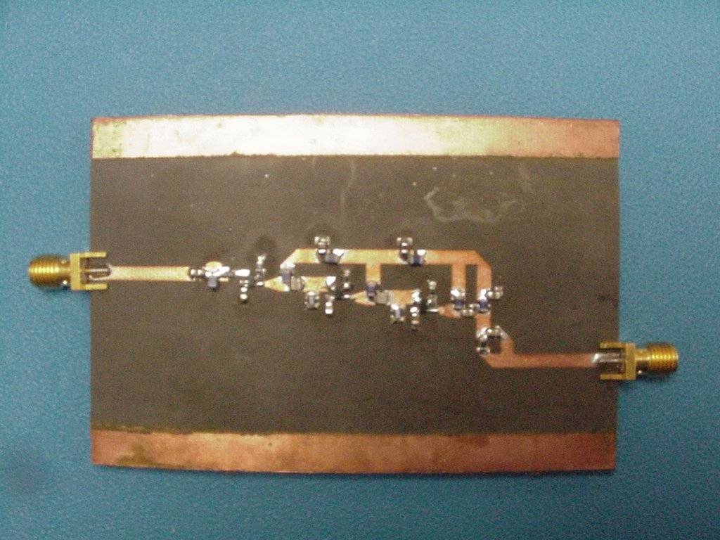
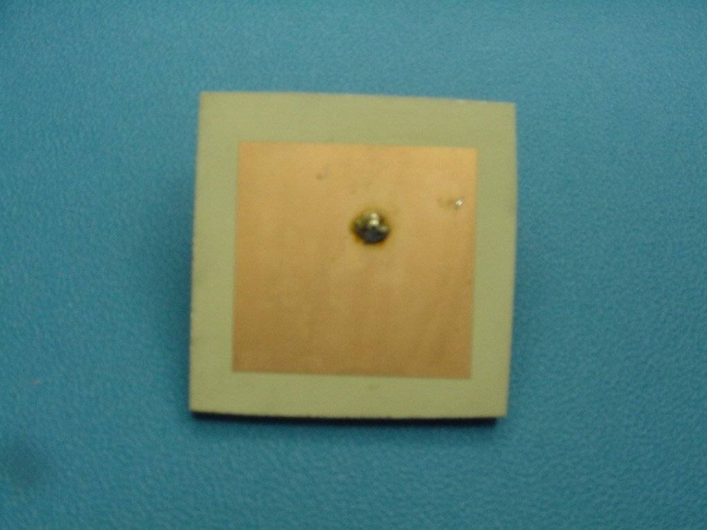
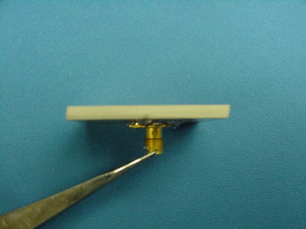
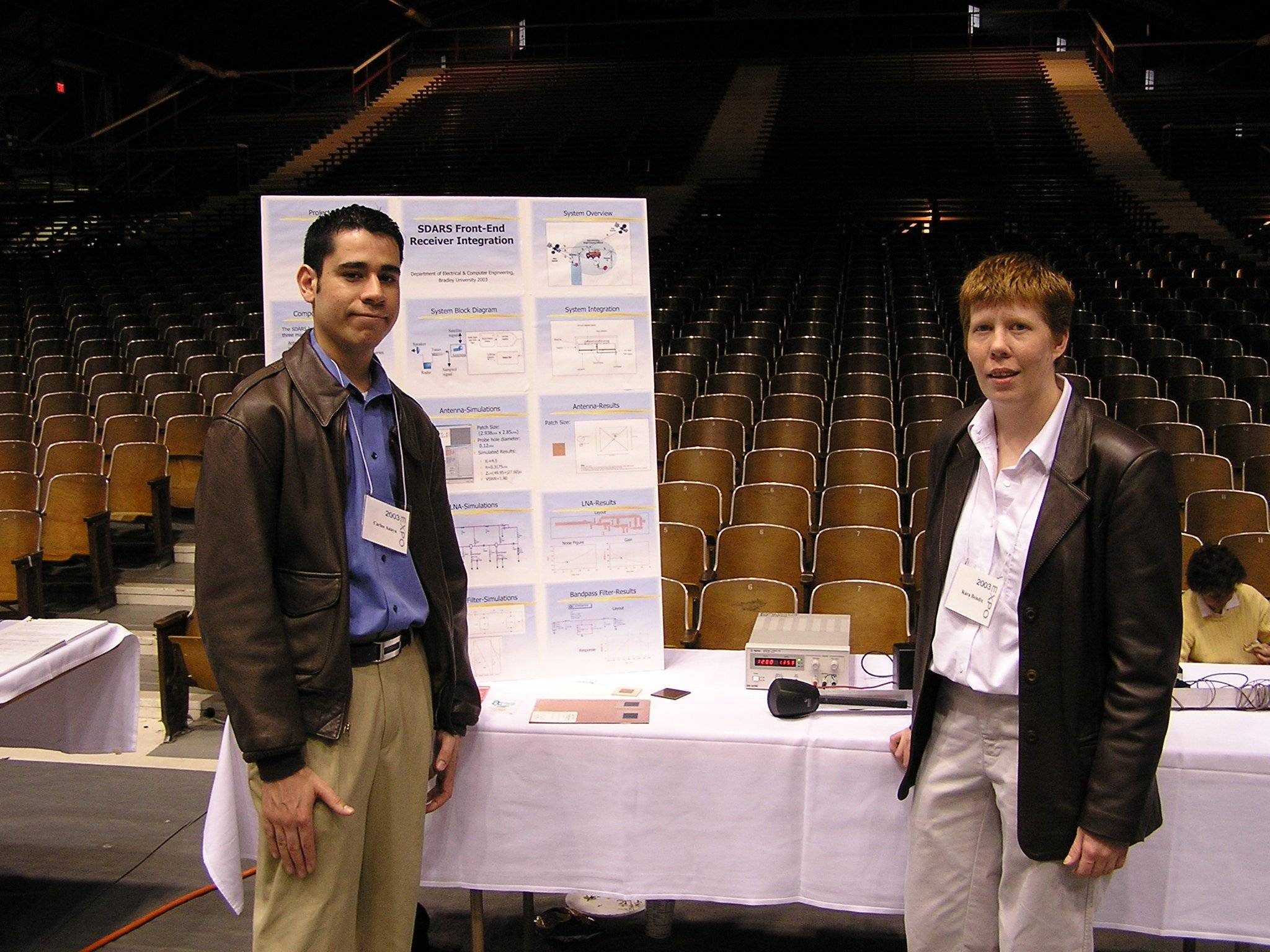
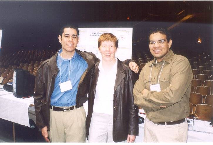
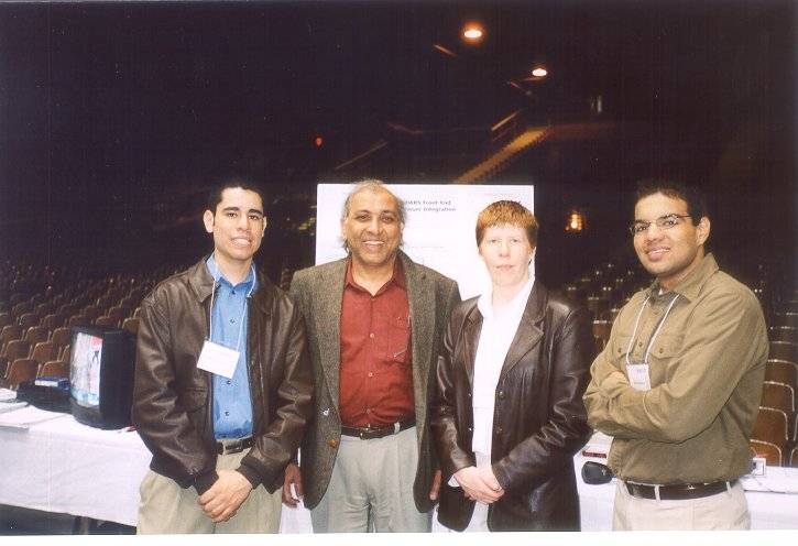
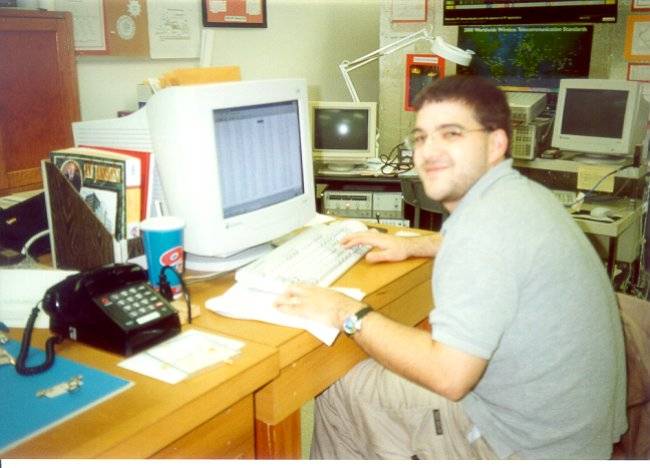
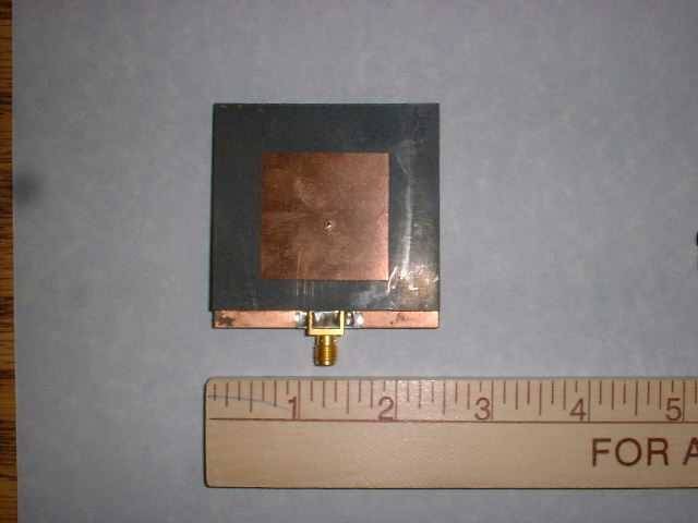
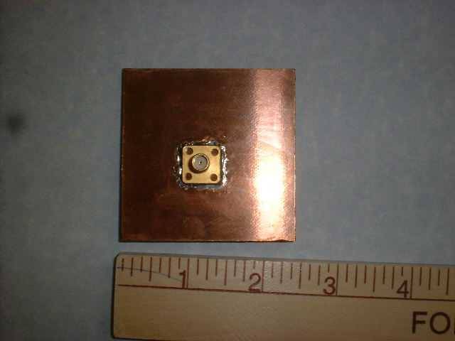
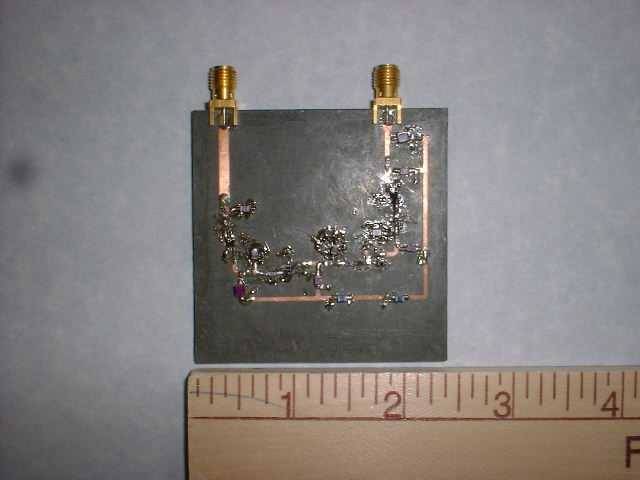
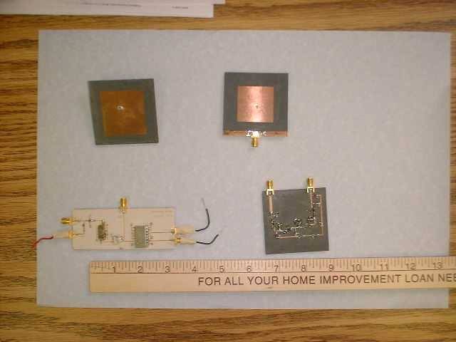
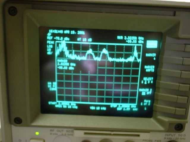
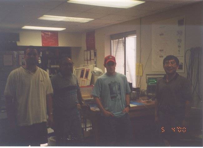
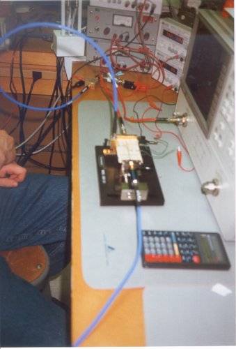
SDARS Front-End Receiver Integration
by : Nitin Malhotra,
Carlos Anaya &
Kara Bendix
Advisor : Dr. Prasad Shastry
May 2003
ABSTRACT
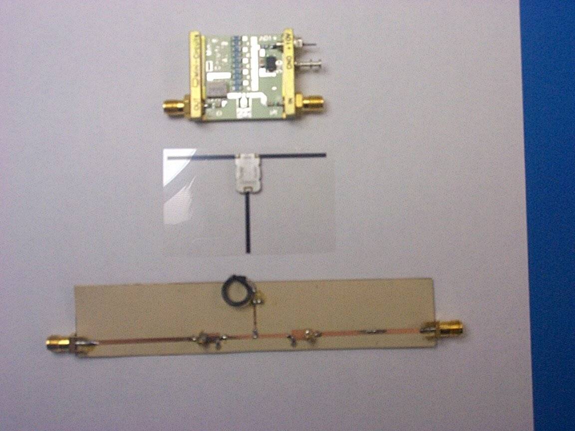
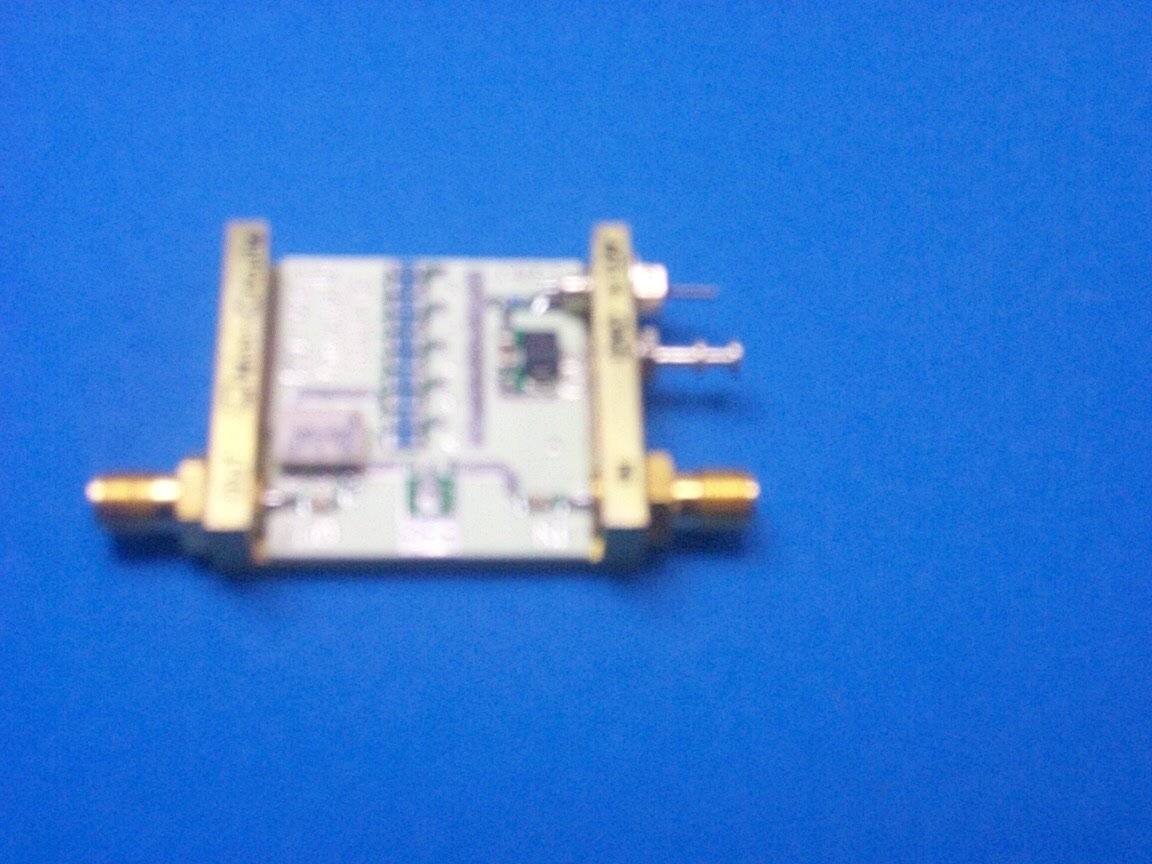
This senior capstone project involves the design, fabrication, testing, and measurements of an integrated receiver
front-end for the SDARS (Satellite Digital Audio Radio Service. The signal originates at the radio studios from
where it is transmitted to the three Sirius satellites that will then broadcast to earth. Ground repeaters are
also implemented to transmit the signal and make possible a clear sound even through tunnels and potential attenuating
factors such as buildings.
A receiver picks up the best input of the broadcasted signals and reproduces the high quality audio contained in the
signal from the satellites. The front-end receiver consists of a circularly polarized antenna, a low-noise amplifier
and a bandpass filter. This project involves the design, test, fabrication and measurements of these components individually
as well as the integrated module consisting of these components
back to list
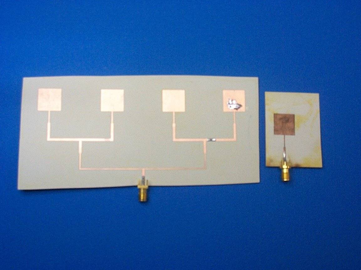
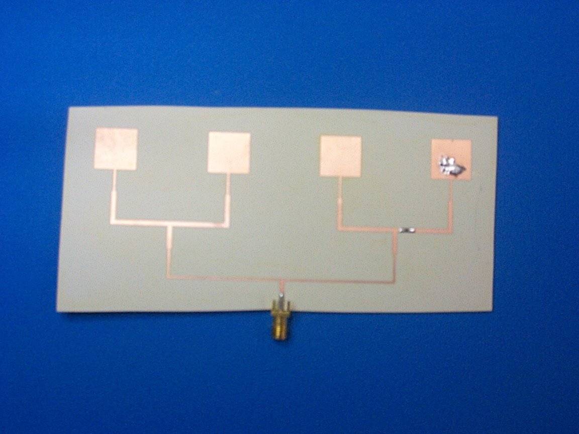
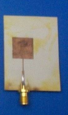
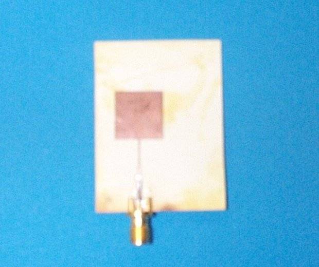
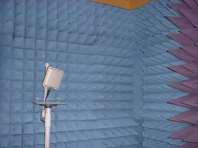
Antenna Array for Automotive Collision Avoidance
by : Mohamed Wagiella &
Tim Carroll
Advisor : Dr. Prasad Shastry
May 2002
ABSTRACT
Driver errors cause a majority of all car accidents. Forward collision avoidance systems aim at avoiding,
or at least mitigating, host vehicle frontal collisions, of which rear-end colissions are one of the most common.
Either warning the driver does this or braking or steering away, respectivelly, where each action requires its own
considerations and design. This senior capstone project involves the design, fabrication, test, and measurements of
antenna array for automotive collision avoidance system.
back to list
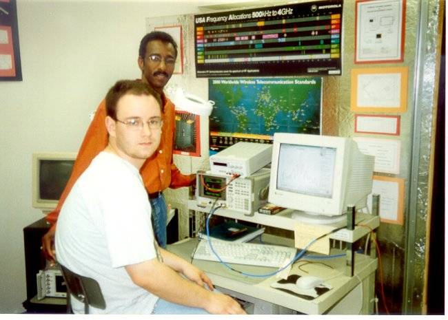
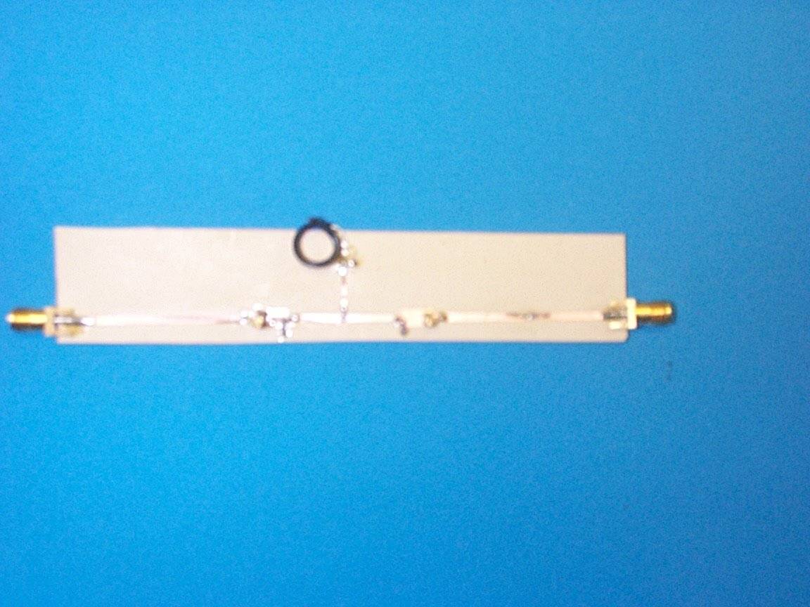
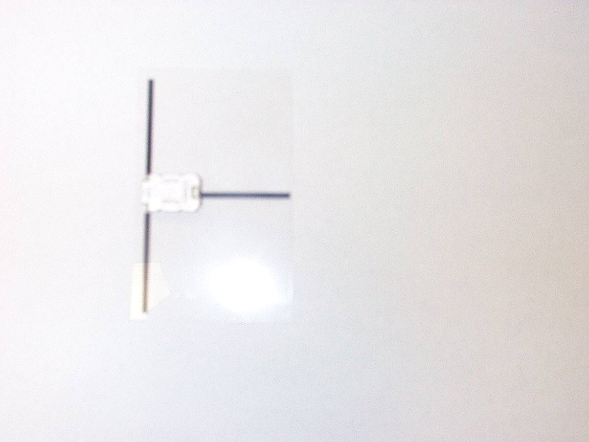
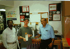
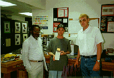
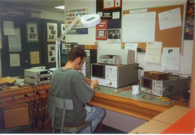
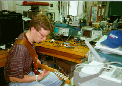
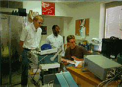
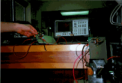
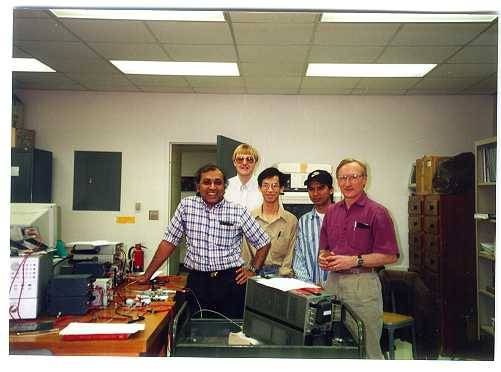
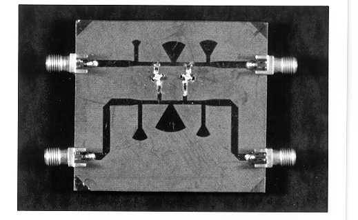
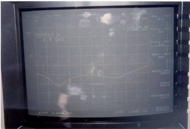
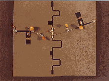
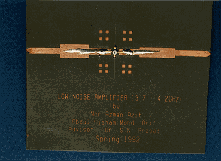
Distributed Amplifier Based Voltage Controlled Oscillator
by : Tim MacShane,
Dane Stivers,
Todd Beyer, &
Monica Studnicki
Advisor : Dr. Prasad Shastry
May 2002
ABSTRACT
Voltage controlled oscillators (VCOs) are an essential to the world of communications.
They work to provide flexibility and stability for public, military, and space communications such as
cellular phones, radar, and satellite communications. As the bandwidth of frequencies that the VCO
can tune to increases, its usefulness increases. Therefore it is imperative to achieve a high tuning
standard. Distributed amplifiers are known quite well for their ability to create a high, steady gain
over a large operating frequency range. The main objective of the capstone project titled
“Distributed Amplifier Based Voltage Controlled Oscillator” is to study the feasibility of using a
distributed amplifier to increase the bandwidth at which the overall system can operate.
|
|
|
|
|
|
|
|
|
|
|
|

|
|
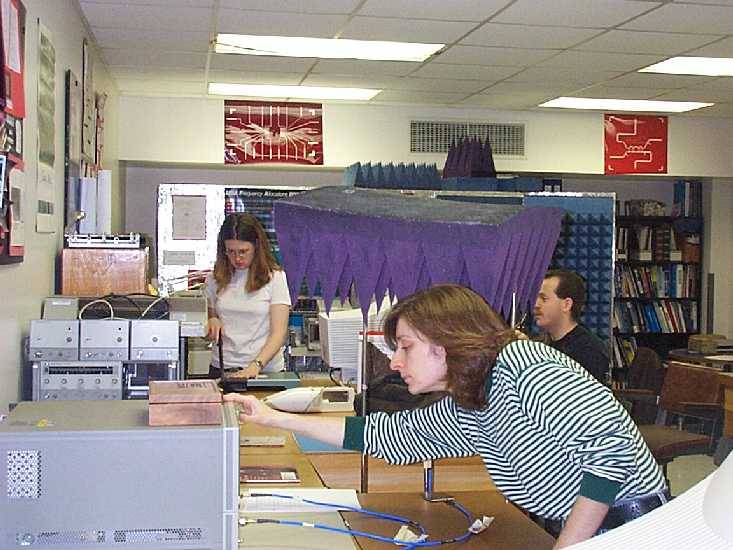
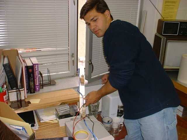
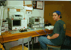
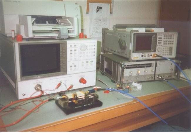
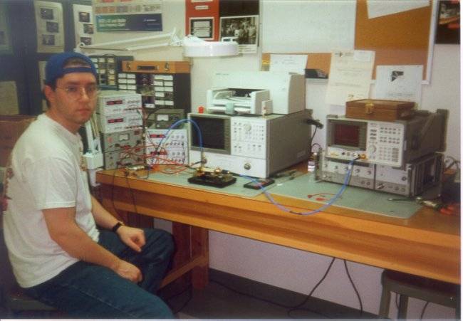
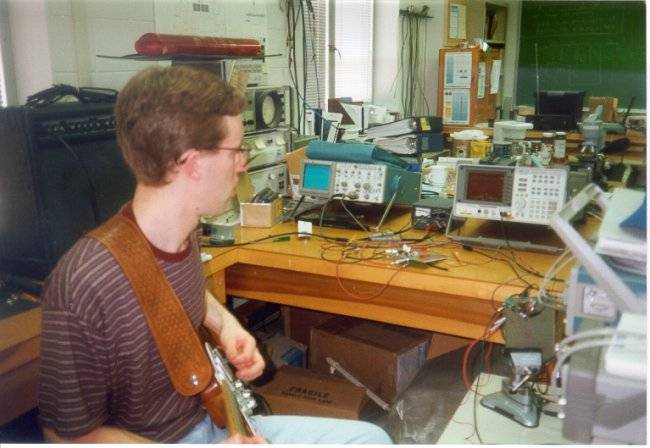
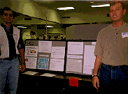
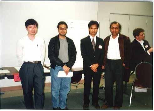
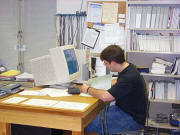
Monica Studnicki, Scarlet Halabi and Timothy MacShane in RF Lab
|
|

|
|
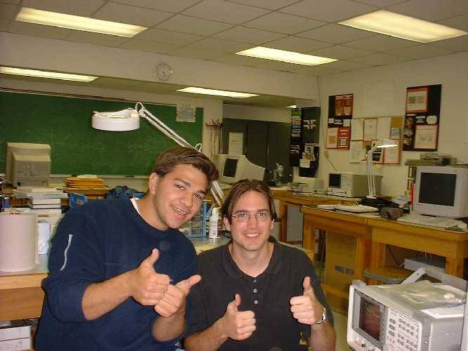
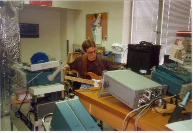
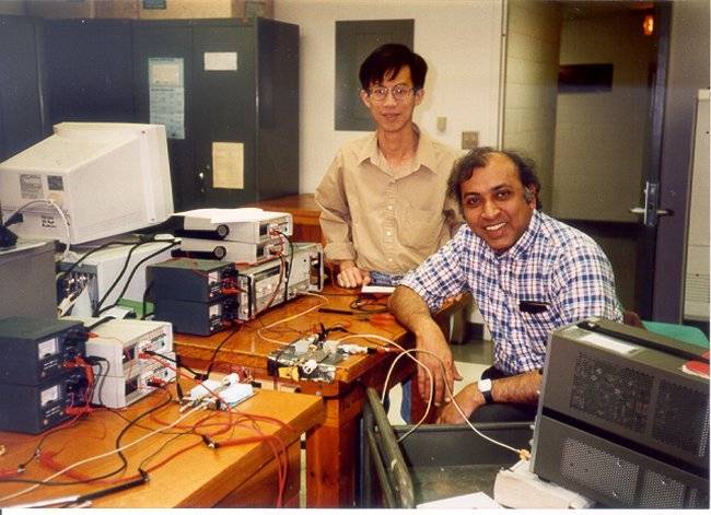
Scarlet Halabi and Timothy MacShane in RF Lab
|
|
|
|
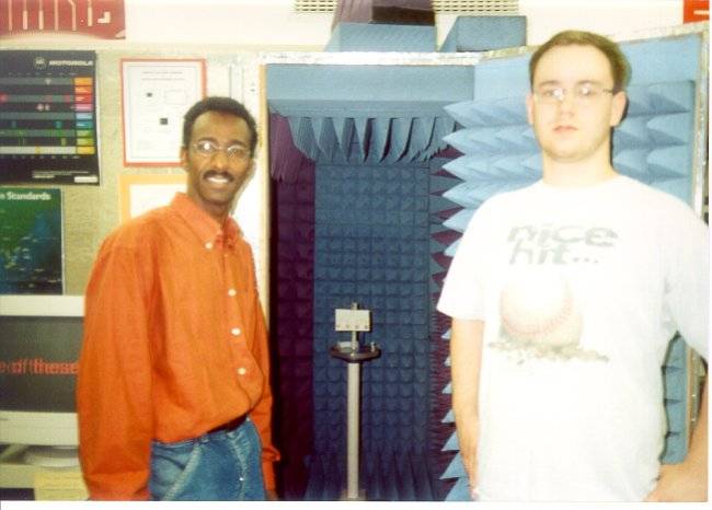
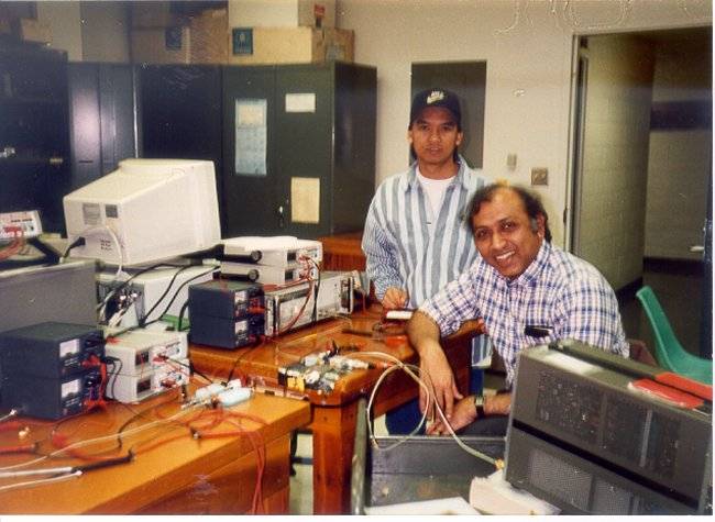
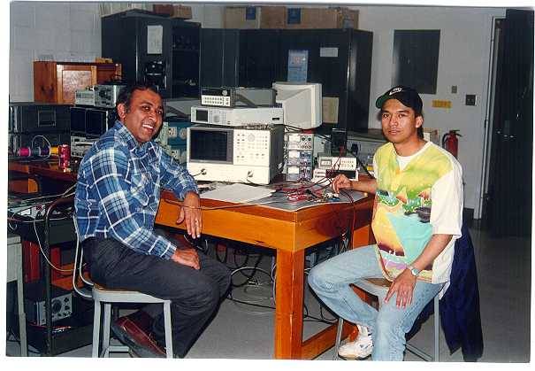
Dane Stivers in RF Lab
|
|
|
back to list
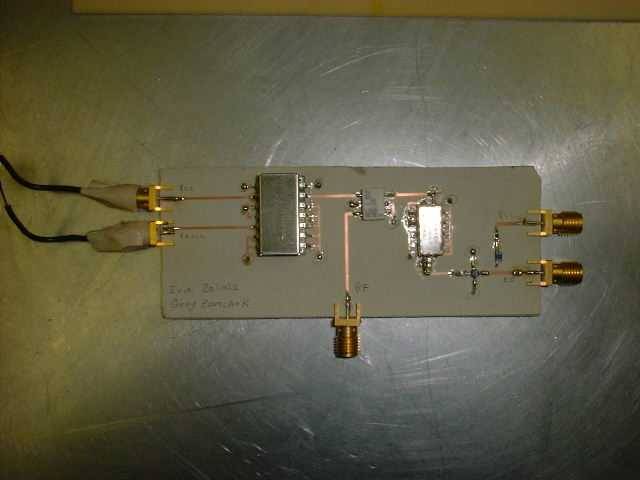
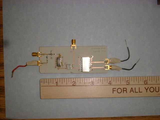
SDARS Front-End Receiver
by : Greg Zomchek &
Erik Zeliasz
Advisor : Dr. Prasad Shastry
May 2001
ABSTRACT
This senior capstone project involves the design, fabrication, test, and measurements of a
front-end receiver for SDARS (Satellite Digital Audio Radio Service). The goal was to receive the SDARS signal
utilizing multiple components to convert it to an intermediate frequency of 70 MHz.
back to list
|
|
Active Duplexer for PCS Transceivers
by : Wesley J. Bond
Advisor : Dr. Prasad Shastry
May 2000
ABSTRACT
In this project, the design and performance
of an active duplexer for a personal communication system (CDMA) operating at
1.9GHz is presented.
The objective of this project is to design an active duplexer for
a wireless CDMA communication system that operates at 1.9GHz. A PCS system already exists
and is incorporating an active duplexer, but this project is to improve the response of the current design.
At the present time the system is using two separate DC voltages to bias the amplifiers.
The goals is to use a unipolar power supply, or in other words just one DC voltage
to bias the amplifiers. Another goals is to incorporate the existing bias-T's onto the circuit board.
back to list
|
Detection and Synchronization in CDMA Receiver
by : Aaron Copeland &
Brian Tranel
Advisor : Dr. Prasad Shastry
May 2000
ABSTRACT
From the Global Positioning System, cellular telephones, direct satellite television,
and now to wireless internet access, digital wireless communication is completely changing the world we live in!
In this project, the design and performance of a Personal Communication System (PCS) Code
Division Multiple Access (CDMA) Receiver to IS-95 standards...more simply, a digital cellular telephone receiver!
CDMA communication systems are based on spread spectrum (SS) techniques that allow many
users to communicate to each other over the same frequency band at the same time because of a unique code assigned to
each user's phone. This spectral efficiency allows for increased user capacity and lower transmission power than
other multiple access technologies such as Frequency Division Multiple Access (FDMA), which assigns a unique frequency
bandwidth for each user, and Time Division Multiple Access (TDMA) that assigns different time slots over the same frequency
bandwidth for all users.
CDMA technology is very complex, and a solid understanding of it's basic principles must be grasped
before one can expect to successfully design and build a CDMA system. This project have covered the main principles involved
for the design of a CDMA PCS cell phone receiver.
This project covered signal spreading using a PN code. This code distinguishes cell sites from each other.
Walsh codes are used to distinguish users from each other. They are important in keeping interference down to a minimum because
of their orthogonal nature.
back to list
900 MHz Wireless Link for Audio Applications
by : Tim Faughn &
Jeff Chesney
Advisor : Dr. B.D. Huggins
Co-Advisor : Dr. Prasad Shastry
May 2000
ABSTRACT
Wireless systems are expanding throughout
the world at an extraordinary pace. They have applications in many electronic
areas including the Internet, personal communications, and audio equipment.
The goal of our senior project is to design and build a wireless audio
link that will transmit a stereosignal from an audio source to a stereo
system so that it can be played on a set of speakers. The system will work
in a transmission range that is in an unlicensed band as defined by the
Federal Communications Commission. The unlicensed ISM band ranges from
902MHz-928MHz.
back to list
Active Microstrip Antenna for GPS
by : Michael Shover
Advisor : Dr. Prasad Shastry
May 1998
ABSTRACT
The project that is described in this report is
the design, fabrication, and testing of an active microstrip antenna. In
an active antenna, an active device such as an amplifier or an oscillator
is integrated with the passive antenna. This particular active antenna
has been designed for use with GPS devices. The two-stage amplifier approach
will be used, since it can provide low noise (<2dB) and high gain (>25dB).
Two GaAs MESFETs are used as the active devices to provide signal gain.
Simulation results from Hewlett Packard's linear simulator EEsof and data
from the tested circuit are presented and discussed.
back to list
|
|
Active Mixer
by : Shawn Parker
Advisor : Dr. Prasad Shastry
May 1998
ABSTRACT
Active mixers have applications in a wide range
of communication systems. In this project, a GaAs MESFET is used as the
active device. Active mixers have a conversion gain. This is an important
advantage over passive diode mixers, which have a conversion loss. This
report will cover the design and testing of an active mixer. The design
issues, specifications, and measured results are presented.
back to list
|
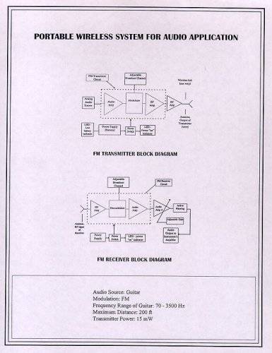
Portable Wireless System for Audio Application
by : David McRell
Advisors : Dr. Prasad Shastry & Dr.B.D. Huggins
May 1998
ABSTRACT
The intent of this project is to design and create
a user-friendly system that transmits the audio signal of a musical instrument
or a microphone to the instrument's amplifier via an analog, wireless communication
link, which thereby replaces the use of cumbersome cords. The transmitter
needs to be portable, and have a broadcast range suitable for its application,
while complying to FCC standards specified by Part 15. Techniques for noise
and distortion reduction, and link budgeting are included in the design.
back to list
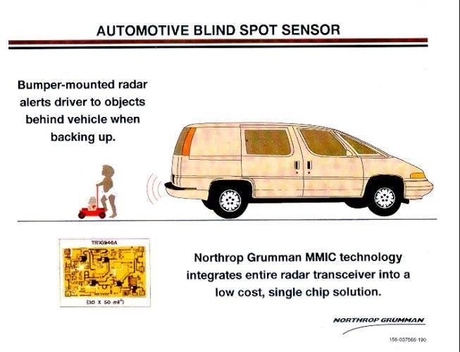
24 GHz Proximity Sensor
by : Bruce E. Unger & Chad Campen
Advisor : Dr. Prasad Shastry
May 1997
ABSTRACT
In today's society, the need for new products to
increase the safety of the individuals is apparent. Several products are
now being developed in the wireless communications industry for this purpose.
The 24GHz Proximity Sensor utilizes radar technology to determine and display
the range of a stationary object with respect to the radar. This project
can affect the world directly, especially in the automotive industry. As
a result of mounting the system on the rear bumper of an automobile, the
range of stationary objects behind the vehicle will be provided to the
driver of the car.
This project is designed around the Northrop Grumman
TR1G946 Monolithic Microwave Integrated Circuit (MMIC) transceiver chip.
Objectives include background research of the radar technology, characterization
of the transceiver chip, and the system design principle to extract the
range information. Utilizing multiple frequency continuous wave radar,
the intermediate frequency output of the transceiver chip is a square wave
if the transmitter signal is switched between two frequencies. The peak
to peak amplitude of the square wave is proportional to the desired range,
which can then be displayed to the driver of the automobile.
back to list
A Compact 2.4 GHz Voltage Control RF Coupler
by : Aaron Dietrich
Advisors : Dr.Santiago Navarro & Dr. Prasad Shastry
May 1997
ABSTRACT
The recent trend in wireless communications product
design has been to make the end product smaller. In order to reduce it's
size, the individual component's sizes need to be decreased. One component
used in RF transceivers that needs to be made small is a matched variable
attenuator. The report introduces the attenuator by discussing a standard
attenuator. A detailed description of the design improvement and testing
procedure using the network analyzer is then discussed in the report. Finally,
the test results of the improved attenuator are compared and contrasted
with the attenuator that was designed and tested last year.
back to list
A 2.4 GHz Matched Variable Attenuator
by : Melissa Anderson & Dana Gardner
Advisors : Dr. Prasad Shastry & Dr.Santiago Navarro
May 1996
ABSTRACT
A 2.4 GHz Matched Variable Attenuator is a part
of a Transceiver Chip used in Personnel Communication Systems. The following
report describes the research and design accomplished in the 2.4 GHz Matched
variable Attenuator project. The report introduces the attenuator by explaining
its functions and applications. A detailed description of the attenuator's
internal Microwave components and the design procedure using HP-EEsof simulation
software is included. Next, the fabrication technique and an explanation
of testing procedures using a network analyzer is discussed. Finally, the
test results of the simulated and fabricated attenuator are compared and
contrasted.
back to list
Linearizing Microwave Amplifier
by : Sean Middleton & Babar Baig
Advisors : Dr. Prasad Shastry & Dr.G.L.Dempsey
May 1996
ABSTRACT
In many RF applications, such as satellite and personnel
communications, there is a need for high power with less distortion. This
project analyzed the problems associated with using high power RF amplifiers
at 4.0 GHz. In order achieve extended input-output power characteristics
of an amplifier, an active feedback methodology was proposed. Design of
the system consisted of a main amplifier, an auxiliary amplifier in the
feedback loop, input and output couplers, and biasing networks. By utilizing
active feedback, non-linearities of the amplifier were reduced and useful
linear range of the amplifier was extended. This project was designed using
the EEsof libra tools and fabricated at the microwave fabrication facility
at Bradley University. Furthermore, final testing proved that active feedback
extends the useful range of the amplifier by approximately 3dB.
back to list
A 2.4 GHz Transmit/Receive module for Wireless Communications
by : Jalmi Shafary Abdul-Jalil & Tuan Tu
Advisor : Dr. Prasad Shastry
May 1995
ABSTRACT
In this senior project report, the design and performance
of a 2.4 GHz Transmit/Receive Module for Wireless Communications
are presented. The results of the simulations as well as experiments as
discussed. The Bi-Directional Amplifier was realized in the hybrid Microwave
Integrated Circuit (MIC) form. EEsof Libra and Academy CAD packages as
well as CAMAD, MSTRIP software were used in the design process.
back to list
The Wireless Group
by : David Baietto, Todd Ciccone, Keith George, Timothy Hahn, & James Menne
Advisors : Dr.I.W.Sennot, Dr.B.D.Huggins, & Dr. Prasad Shastry
May 1995
ABSTRACT
The field of wireless communication is rapidly expanding
with the emergence of personal pagers, cellular mobile radio systems, vehicle
tracking, and commercial use of GPS. Multipath and interference from other
users are the two basic problems the designer must face. Spread Spectrum,
Code Division Multiple Access (CDMA), is proving to be available technique
for modern wireless communications due to its ability to efficiently incorporate
many users within a relatively wide bandwidth. It was the Wireless Group's
intention to design, construct, and test a network for wireless communication
using spread spectrum. The goal was to make a network capable of transmitting
information from a portable user unit to a receiving base station. Possible
continuations of this project could involve the addition of a number of
users in a two-way communication link.
back to list
A 2.4 GHz Transceiver For Wireless Communications
by : Eric Haakenson
Advisors : Dr. Prasad Shastry
May 1994
ABSTRACT
Wireless communication refers to the new technology of replacing phone lines by
transmitting voice and data through the air at lower microwave frequencies (2.0 - 4.0 GHz).
This frequency band has been allocated by the FCC for Personal Communication Systems (PCS),
Wireless Local Area Networks (LAN) and wireless television. This Project entails testing
and running Northrop's 2.4 GHz MMIC Transceiver for Wireless Communications. One aspect of
the project entails design and fabrication of a microwave circuit board to test the Transceiver chip.
It also entails design, fabrication and testing of passive components such as microstrip bandpass
filters, power dividers, and lumped element impedance matching networks. The designs of the
circuits as well as results of test and measurement will be presented.
back to list
A 2.4 GHz Electronic Tether: Digital Subsystem
by : Jeff DeMott & Luke Moranda
Advisors : Dr.I.W.Sennot & Dr.B.D.Huggins
May 1994
ABSTRACT
Monitoring a young child in a crowded public area can be a difficult job.
The electronic tether addresses this problem. The electronic tether is a child monitoring
device which measures the distance between the child and parent, setting off an alarm to
alert the parent when the child has wondered too far away. Existing systems that attempt
this distance measurement are based on estimating propagation loss. This has proven to be
inaccurate due to interference, multipath, and varying component attenuations. Using more
sophisticated correlation techniques, the dependency of the measurements upon signal strength
has been eliminated. Measuring the correlation between two reference signals and the received
signal delayed by the round-trip path delay, yields an accurate distance measurement.
back to list
A 2.4 GHz Electronic Tether: RF Subsystem
by : Len Bergman & Sterling Toedtemeier
Advisors : Dr.I.W.Sennot & Dr.B.D.Huggins
May 1994
ABSTRACT
As society grows, parents become more concerned for the security of
their children. The "Electronic Tether" assists parents in keeping track of where their
children are located. This is a joint project broken into three subsystems: RF (radio frequency),
Digital Systems, and Power. Communication was accomplished between the child's unit and
the parent's unit by an RF link at 2.4 GHz. Through the use of microstrip and microstrip
surface mount components a PRN code was modulated onto a 2.4 GHz signal and transmitted.
At the receiver correlation data and distance information was determined by the use of a
system constructed from surface mount mixers, SAW filters, and VCO's.
back to list
A 2.4 GHz Electronic Tether: Power Subsystem
by : Dave McDermott
Advisors : Dr.I.W.Sennot & Dr.B.D.Huggins
May 1994
ABSTRACT
The electronic tether project consists of an interrogator and transponder
unit which are both portable. The interrogator is powered by two AA batteries and the transponder
by two button cell batteries. The interrogator unit consists of digital components including a
microprocessor, two VCOs, and RF equipment. These VC0s have an equivalent load of 167 ohms while
operating at 3 V and the microprocessor is 333 ohms at 5V. For this reason, there are two DC to
DC up converters on the interrogator which maintain constant output until the input level drops
beneath 1.6V. The transponder consists of digital components and one VCO. One DC to DC converter
is required for the 3 V required by the VCO. The converters have low power indicators which trigger
an alarm when the input voltage falls beneath 2V.
back to list
|
|
A 4 GHz FET Power Amplifier
by : Ismail Mazlan
Advisor : Dr. Prasad Shastry
May 1993
ABSTRACT
In this report the design and performance of a GaAs
FET Power Amplifier in the range 3.7 to 4.2 GHz are presented. The results
of simulations and experiments are discussed. The amplifier was realized
in the hybrid MIC form. EEsof Touchstone, Libra and Academy CAD packages
as well as MATCHNET software were used in the design process.
back to list
|
|
|
4 GHz GaAs FET Low-Noise Amplifier
by : Abdul Hisham Mohd Arif & Nor Azman Azit
Advisor : Dr. Prasad Shastry
May 1993
ABSTRACT
In this report the design and performance of a GaAs
FET Low-Noise Amplifier in the range from 3.7 to 4.2 GHz are presented.
The results of simulation as well as experiment are discussed. The amplifier
was realized in the hybrid MIC form. EEsof Touchstone and Academy CAD packages
were used in this design process.
back to list
|
A Push-Pull Distributed Microwave Amplifier
by : G.Brubaker
Advisor : Dr. Prasad Shastry
May 1992
ABSTRACT
The Push-Pull Distributed Microwave Amplifier is
composed of several amplifier stages. First, a description of the fundamental
concepts of the amplifier will be presented in order to clarify its operation
and design considerations. Second, the amplifier will be subdivided into
'cells' which will facilitate design and analysis considerations. Finally,
with the amplifier cell sections connected together, the operation of the
complete amplifier will be discussed and the results of the computer-aided
simulations of the 2-6 GHz amplifier will be presented.
back to list
 Back to the ECE Microwave home page
Page Manager:
Sairaj Anantoju