Microgrid ESS Sizing
1. Introduction
Microgrids are small independent power grids that are used primarily to provide power to remote locations. They consist of several major components which include a generator (genset), photovoltaic arrays (PV), a Microgrid Master Controller (MMC), and Energy Storage Systems (ESS) among other components such as various forms of renewable energy. ESS sizing is currently a manual process at Caterpillar’s Division of Electric Power, which is time consuming, inaccurate, and expensive. Not only does this process involve an engineer making time consuming assumptions, but if these systems are oversized, the result will be a greater cost to Caterpillar’s customers. This project involves automating the process for a cost effective and efficient sizing solution. This can be accomplished by developing a model that has inputs for all the major factors affecting ESS capacity, and gives an output of the necessary ESS capacity for that system configuration. The model will be validated by running multiple tests on an actual microgrid system to see if the ESS size determined will meet the necessary criterion both from the model and the test situation on an actual microgrid. Figure 1 below shows a high level block diagram of a simple microgrid system with an ESS.
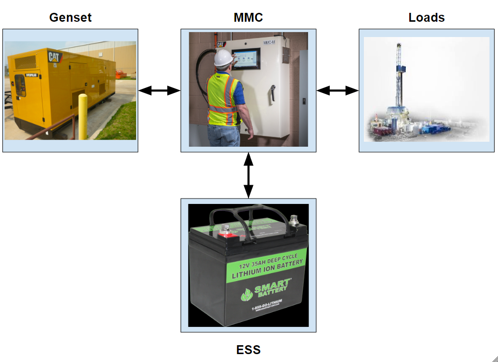
Figure 1: Basic High-level Microgrid System
2. Background and Motivation
Background: The U.S. Department of Energy (DOE) has provided the following definition of Microgrids: “A Microgrid is a local energy network that offers integration of distributed energy resources (DER) with local elastic loads, which can operate in parallel with the grid or in an intentional island mode to provide a customized level of high reliability and resilience to grid disturbances. This advanced, integrated distribution system addresses the need for application in locations with electric supply and/or delivery constraints, in remote sites, and for protection of critical loads and economically sensitive development [1]”.
A microgrid includes the DER, energy storage system, and loads. DERs can be divided into two main groups:
- DER directly coupled conventional rotating machines
- DER grid-coupled with the inverter
The first main group will be the focus of this project because the system will not be tied to the main grid but will be connected to a genset.
ESS can be charged through the excess power and discharged when there is a power deficit. Therefore, the energy storage system enhances the reliability of the microgrid as well as making it more economical by storing excess energy to be used at a later time. Another benefit of the energy storage system is the ability to prevent transient instability and take part in controlling the voltage and frequency of the microgrid, providing a balanced system. This is known as grid stabilization and droop control.
Figure 2 shows the basic components to the microgrid available from Caterpillar dealers. These components were previously mentioned in the simple microgrid model depicted in Figure 1, with the exception of the remote monitoring system and the Microgrid Master Controller (MMC). The project will not focus on these components so they will not need to be discussed in detail or modeled in the simulations.
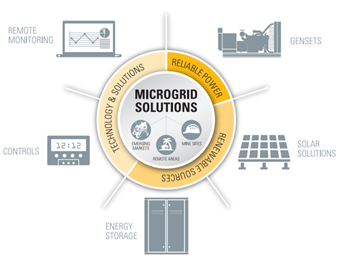
Figure 2: Depiction of the general components of the microgrid
Microgrids can operate in two different modes:
- Island Mode
- Grid-connected Mode
The mode that pertains to this project is island mode. Island is when the microgrid can operate autonomously in a similar way to that of an electric power plant but on a small scale.
There are a few aspects of a microgrid to consider in order for it to be operating in an optimal way. These include such considerations as technical, economical, and environmental aspects of efficiency. The technical aspects have been briefly discussed earlier (DER, energy storage system, and loads), in relation to grid stabilization and droop control. The economics will be touched on briefly because the client would like the team to study HOMER, which is a tool used by Caterpillar for economic analysis of microgrids. The environmental aspects will not be addressed in the report because it is outside the scope of the project.
DISTRIBUTED ENERGY RESOURCES
“Distributed Energy Resources (DER) are smaller power sources that can be aggregated together to provide the power to meet the total demand. As microgrids continue to modernize, DERs such as storage and advanced renewable technologies can help facilitate the transition to a smarter grid [2]”. Caterpillar’s microgrid systems utilize gensets and photovoltaic arrays as the source of DER. The photovoltaics are not going to be discussed in this paper because that is out of the scope of the project.
GENSET
“Reciprocating-engine generator sets can deliver reliable energy and are fully dispatchable. This is useful because while renewable energy sources are offline or producing at less than rated capacity, the genset can make up the difference to supply the correct power to the load. Units in ratings ranging from 350 kW to 15 MW or larger are available from Caterpillar dealers, and can be connected together in a modular fashion to create systems of substantial size [3]”. These gensets have been determined to tolerate a wide range of ambient temperatures as well as high altitudes without their ratings decreasing. The gensets designed by Caterpillar can withstand quite a large number of starts and stops with minimal impact on service life. The gensets will turn on when the ESS and renewables are not producing enough power, and off when other DERs can deliver sufficient power to the load.
ENERGY STORAGE SYSTEM (ESS)
The Energy Storage System (ESS) is used for integrating the renewable energy sources with the gensets. The version of ESS that Caterpillar uses is Lithium-Ion batteries and some combination of ultracapacitors. The ESS must be sized based on the capacity that is needed to stabilize the Microgrid and keep the voltage and frequency dip without a specified tolerable error.
Motivation: As aforementioned, a basic microgrid system typically consists of a genset, a master controller, and a load. The purpose of the ESS in the system is to reduce the droop of the transients before the system reaches a steady-state value known as grid stabilization. Due to the mechanical nature of the Genset system, a problem known as the droop control problem occurs. This happens when significantly large step loads or large changes in the dynamic load profile, are applied to the system. When a large load is suddenly applied, the engine RPM will decrease resulting in lower output voltage and frequency for a short time until the genset can regain its original speed. Additionally, if a large load is removed from the system, the excess energy from Genset at that high generation state will cause the voltage and frequency to spike as the load is removed. A larger genset could be used to reduce the tendency to slow down when heavily loaded, but that upgrade would be quite costly. An effective way to reduce droop is by the application of ESS to the system. This will allow the genset to operate at a relatively consistent speed when a large step load is applied because the excess energy needed, is provided from the ESS. Figure 2 is an example of what the result looks like when ESS is applied to the system. On the left, there is no ESS and a 520 kW step load is applied directly to a 500 kW genset. The result is large voltage and frequency dip before the generator gets back up to steady-state speed. On the right is the same genset but this time with a 750 kW ESS and a much greater step load of 1.5 MW. The result is a much smoother voltage and frequency transition with minimal droop, even though the load was nearly tripled. If the 520kW load was also used in the test on the right of the figure, the droop would be almost negligible.
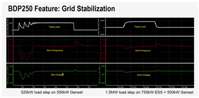
Figure 3: Grid stabilization by adding an ESS into system
3. Problem Statement
The main research goal of this project is to provide a solution to ESS sizing based on custom requirements. There are two phases in this research.
PHASE ONE
The main focus of phase one is the ESS sizer, but there are many subtasks which must also be completed. The first task will be to analyze and understand the methodologies of the genset SpecSizer. The team will study the current method for ESS sizing. The team plans to create a model in Simulink of our ESS sizing solution to prototype and test the ESS sizing logic. The initially developed model will be fully tested through a series of tests with actual microgrid components to fine tune the model into a satisfactory final version. This model will be the major deliverable for phase 1 of the project, which will eventually be implemented into the Specsizer web application by Caterpillar. The testing will take place at TDI facilities in Morton, IL where Caterpillar has equipment for testing purposes such as gensets, ESS systems, and loads. In developing our solution, the team will research other companies who are doing similar work to see how they size their systems.
PHASE TWO
The second phase is more focused on the economic requirements of ESS sizing. First, the team
must fully understand HOMER and what it does. HOMER is the program used to model the economical aspects of practical microgrids. The team may use HOMER’s results to improve the outputs of the ESS SpecSizer. To improve the functionality of HOMER the team must analyze the default MMC that HOMER uses and how HOMER uses it. The team will also analyze the CAT dispatcher and may create a Simulink model in order to create a plugin for HOMER. This plugin will be used in place of the default dispatcher to improve HOMER’s results so that they more accurately represent Caterpillar’s microgrid performance. The plugin is a stretch goal for the team, because time constraints for the semester may not allow for development of the plugin. The team will also research the competition to see how other companies execute similar tasks, and if they have better ways of doing so.
4. Functional Requirements
SYSTEM LEVEL
The goal of the system as seen Figure 3 is to size an ESS system so that the Genset droop levels are maintained within a specific range as the grid experiences a variation in power. Microgrid ESS systems are composed of Li-ion batteries, ultra-capacitors, or some combination of the two, that will bring the droop within the required specifications for a given load. Genset size and output capacity will be an important input to the system because it is the primary source of energy in simple microgrid systems such as the one depicted by the diagram in Figure 1. The second most important factor in the sizing algorithm is the size of the applied step load or load profile change. This is critical because a small load and a large genset will require a very small ESS system for supplementary energy if it is needed at all. Conversely, if the genset is very small compared to the load size, a huge amount of energy storage will be needed to keep the droop within acceptable limits. There will be a cost analysis involved with these two scenarios because if either the genset or the ESS system becomes unnecessarily large, the cost will be very high. Finally, the load type is important (resistive and/or reactive) because of the nature of the transients on differing loads. In some cases the transients may take a long time to reach steady state. To compensate, the ESS needs to supply enough energy to make up the difference in order to maintain a clean signal with desired droop. Figure 3 below gives a simple block diagram of what a high level sizing algorithm could look like for determining the necessary ESS for the system. The step load size and load type inputs could be combined together as a single load profile input. Some of the proposed methods make use of a load profile and some just use a step load. We are interested in sizing ESS for all cases, but the starting point and initial algorithm prototype will deal only with step loads.
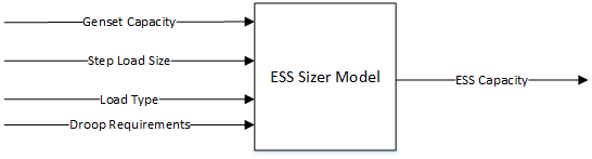
Figure 4: A simple high level diagram of a sizing model
POTENTIAL SIZING ALGORITHMS
The following algorithms are the main techniques proposed by the team to be able to determine the proper ESS size for the given genset. These algorithms will follow a generic flowchart similar to the one included in Figure 5. The solutions will be obtained by implementing the mathematical equations and decision processes in a scripting language such as MATLAB. The algorithms have been narrowed down through research, to several that may be prototyped and tested against each other. These include some variation of particle swarm optimization, genetic algorithms, and discrete fourier transforms (DFT).
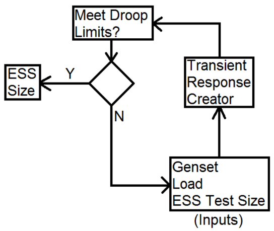
Figure 5: A high level flowchart of the basic sizing decisions
The first step in the schematic of Figure 5 is to supply the inputs such as all the parameters of the gensets, loads, and an ESS test size. Once the parameters are given, the information then goes to the transient response creator to simulate how much droop there is when adding load. Once that is done the droop calculation goes through a decision matrix to determine if the correct ESS has been selected. If the droop criteria isn’t met, the algorithm will go through the process again until it finds the correct ESS for the microgrid. The input box has yet another layer to it. Within this box the team is trying to create an efficient way to determine ESS test sizes based on the capability curve of the BDP250 inverter and storage capacity of each ESS. Also, after this method has been proven to work, the team will add in another penalty requirement much like the droop requirement, that will make a decision on the ESS based on whether or not the test system achieves stability within the desired time frame of 10 seconds, the time defined by the client as the maximum for any grid stabilization feature.
Chaotic Binary Particle Swarm Optimization
Particle swarm optimization is a stochastic population-based evolutionary algorithm (PSO) [6]. For discrete systems, binary particle swarm (DPSO) optimization is used. Both of these optimization techniques allow ease of optimization for nonlinear multivariable systems. Chaotic DPSO adds the stochastic nature of microgrids into the equations. It may be sufficient to use just DPSO initially because the team’s project does not concern PV arrays. The steps to performing Chaotic DPSO are the following [6]: (1) Input initial conditions and sizes of the variables, size of the swarm, and other parameters of the PSO technique. (2) Distribute chaotic variables uniformly between 0 and 1. (3) determine fitness of function. (4) Update position and velocity of particles. (5) Calculate the distance between an arbitrary particle and the current best particle, if the distance is within the predetermined minimum distance that particle remains unchanged in the next iteration. (6) Check if state of particles meet constraints. (7) If constraints are met, stop the process, otherwise go back to step 3. PSO algorithms work within some predefined boundaries to locate a global optima. The drawbacks of this method include the following: (1) the particle swarm is not guaranteed to converge on the global minimum, (2) iterations can be time consuming depending the size of the data set, (3) function boundaries must be defined and may be difficult to be determined.
Genetic Algorithms
GAs are the family of algorithms used to solve optimization problems in a way that resembles biological evolution. The process in a typical GA as in [7], consists of a series of five steps in which the result is the global minima of the function being optimized. The steps include choosing a random initial population, individual evaluation, parental chromosome selection, crossover and mutation, and iteration and termination. These steps can be repeatedly iterated through until a point of termination is reached which will result in the best optimization. This technique can be used for discontinuous and nondifferentiable functions which are some situations that are difficult to perform with other conventional algorithms.
Discrete Fourier Transform
Gensets have a low frequency response rate when compared to an ESS. There must be an allocation of energy between the fast response of the ESS, and the slow high power output of the genset. In [5] it was proposed to use a discrete fourier transform (DFT) to analyze the frequency domain responses of both the genset and the ESS. First, the allocation of the balance of power between the ESS and the genset, and the optimal cutoff frequency is determined using DFT. Then, the inverse discrete fourier transform (IDFT) is used on the results to obtain the power allocation in the time domain. Figure 6 shows a simple high-level flowchart of the algorithm steps.
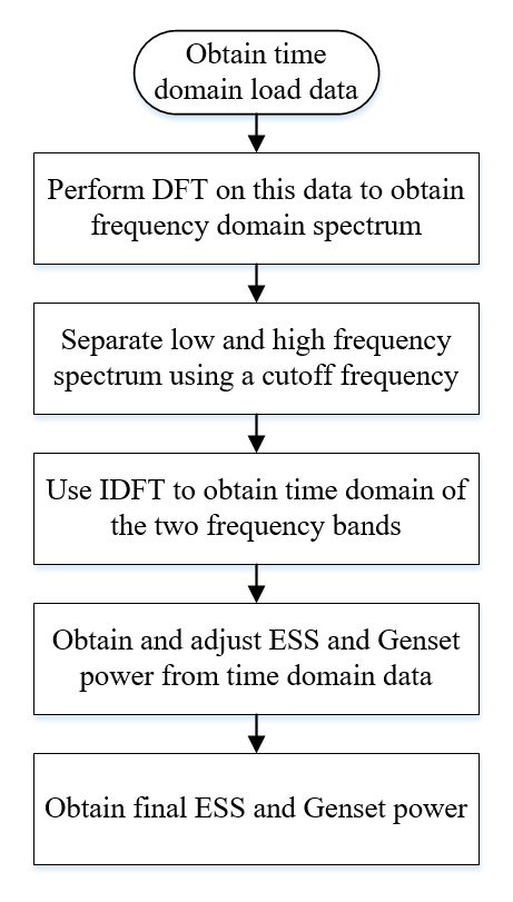
Figure 6: DFT method
Linear Programming Optimization
ESS sizing can be performed using the ideas proposed in [9]. A cost function J(Es) must be defined for the application given by the client. The cost function defined in [9] is the sum of the energy produced from load, genset, and ESS, plus the sum of the size of the ESSs. Once the constraints are determined to meet droop specifications and voltage limits, this J(Es) can be minimized using linear programming.
SUBSYSTEM LEVEL
ESS Physical Array Considerations
Any number of Lithium-ion cells and/or ultracapacitors may be encompassed in an ESS. The exact number depends on load requirements, the size of the genset, and the type of loads that are on the grid. Through research the team has found that the best approach is to allow all the cells to be at approximately the same level of charge in order to operate more efficiently. We must develop a way to measure charge status of each battery cell. This will allow us to quickly identify any problems that might arise with the individual cells. Another important feature will be allowing communication among the cells. This allows us to maintain a balanced charge across the whole system. Feedback from the cells can help catch potential failure in the system caused by an individual cell. Another important consideration is how close actual ESS systems can get to the capacity that will be predicted. It is important to note that the capacity of the ESS can be adjusted by adding or removing batteries. Battery cells are connected together in a series/parallel combination where the number of series cells determines the desired voltage and the number of parallel branches determines the ESS capacity. After a capacity is determined for the ESS, the algorithm can check a table of available options and choose the one that is just above the actual size determined.
ESS Charge Level Considerations
Another subsystem will be the size of the ESS in relation to the capacity of the genset in light of the frequency of applying large step loads to the system. If large step loads are applied to the system very frequently, and the genset is too small, there will not be sufficient time to recharge the ESS system before a new step load is applied. This leads to the question of the State of Charge (SoC) for the ESS at any given time, and whether the genset is large enough to support a large number of voltage steps.
The ESS system is one of the subsystem blocks that will be modeled in Simulink as part of the algorithm validation process. After each of the algorithm prototypes are developed and ran through trial tests, it is desired to compare them with similar tests in a microgrid Simulink model. For some of the components, common Simulink blocks will be used while in other cases, the blocks will need to be developed from subblocks or modify existing models. Figure 7 gives the Simulink block that would be used to simulate the ESS portion of the microgrid. This block has some configuration parameters such as voltage, battery type, charge level, and charge rate so it can be quickly adjusted to simulate various ESS installations and their system behavior.
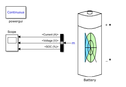
Figure 7: A Simulink ESS model which will be integrated with a three-phase inverter (BDP)
Genset Mechanical Considerations
While the genset has a rated capacity, since it is a mechanical device, there are quite a few other factors that must be considered relating to the genset dynamics. For example, the speed and torque of the engine will be affected by such things as ambient temperature, altitude, and fuel type. These conditions must be monitored because reduced engine speed will cause the genset output frequency to be reduced as well as if the engine torque is lowered the genset output power will also be lowered. Different site and load conditions are currently being considered in Specsizer when the genset is being sized but they will also be important in the case of sizing ESS for a particular genset and later for deciding which genset and ESS combination is the most cost effective choice. The genset will be modeled in Simulink for validation purposes using a modified version of the G3516 diesel genset model supplied by the client. Some parameters can be changed in the model so that it will behave as a G3512 which is the first genset the client would like to be validated. Figure 8 is the genset Simulink model that will be used in the simulations.
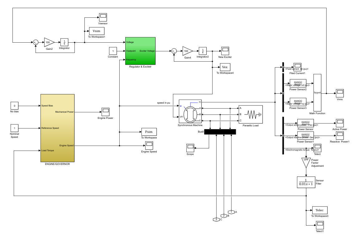
Figure 8: Genset model supplied by the client
CONCEPT 1
One concept that we were not sure would be beneficial was to utilize the creation of a transfer function. This transfer function would describe the system response and be able to be solved for the ESS size. The steps to take in order to arrive at a transfer function that would correctly model the microgrid system are unknown. However, this area should be further researched, as we will need equations that define system behavior in or to run some of the optimization algorithms.
CONCEPT 2
There are a few ideas and stepping stones with which we have decided to pave the path toward success. These tasks have not only been chosen to best accomplish our task, but also to share the work among the team. The first step that will be taken by the ME side of the team is to gather test data and technical specs from CAT and TDI. The first step taken by the EE side of the team is to create a model of a genset, ESS, and variable load system in MATLAB/Simulink. Both teams will work in parallel and share results. The test data collected from the system at TDI will be used to design the methodology and to verify tests run on the modeled system. The model created will be used to run a large number of test conditions on the system by changing the load and ESS size to understand the transient response of many configurations. After or while data is gathered on transient response, the ME side will begin laying groundwork for the selection methodology itself. The “rules of thumb” currently utilized by the engineers that size ESS are known. These rules are to have 75% of the load covered by the ESS at start, to have minimal droop, maintain a stable system within 10 seconds, and be limited by the BDP250 Inverter capability. An even better understanding of the manual process will be sought after. We wish to watch an engineer manually size an ESS with the 3512 Genset in order to analyze the methodology. Using patterns found in the manual methods as well as the algorithms employed in the genset specsizer we hope to create an algorithm that will be able to size an ESS with the G3512 Genset to handle various loads. The results will be tested on our model if it is not possible to test at TDI. This will be our baseline/proof of concept. From this, we will hopefully be able to expand the capabilities to have a variable genset as well as ESS.
5. Research Plan
Research will be done on existing models used for sizing ESS in microgrids. Mathematical models and Simulink models will be considered. Mathworks provides a simplified model of a small scale microgrid[1]. The simplified model can be altered to simulate a microgrid using the various component blocks and apply load profiles provided by Caterpillar for various applications such as drilling and mining sites. The model must be modified to simulate Caterpillar’s G3512 genset instead of a power grid so that a relevant system can be analyzed. Caterpillar has made available an ESS and Genset test facility using the G3512 which is why this will be the chosen model for preliminary testing of models and algorithms. This ESS is made up of three different cells with a capacity of 250 KW each. This will let us test a constant load with different sizes of ESS. The results of these tests will give us a better idea about the transient response. The team can then begin adjusting the ESS size in the simulation to see how droop is affected. After preliminary study of this specific application, we can look into different load profiles and other gensets. Once the study using simulink is complete, the team can then start determining strategies to size ESS for many different microgrid situations.
6. Preliminary Results
The team started with simulating the results from [5]. Seeing as how we don't have robust models for the components, we decided that using the DFT method might be the best in this situation. We started by applying the method to a step load. We know that a step load is a hypothetical situation, but the responses might have some indications to how the method is operating in a worst case scenario. In figure 9 below is a step load with a cutoff frequency chosen at 20 samples.
When we applied the step load, the system has a huge spike to deal with. Since the generator cannot handle high frequency fluctuations, the ESS would need to supply most of the energy. We still see some generator contribution at the low cutoff that we set, but the ESS trying to supply most of the load. The spike in the ESS in the time domain is at a very high frequency. The results from this simulation are questionable since we know that the ESS cannot handle frequency fluctuations that are too high, but we do observe that the method is trying to match whatever the load profile requires.
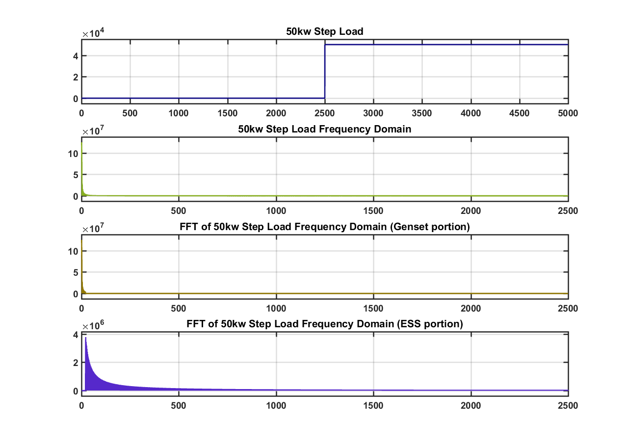
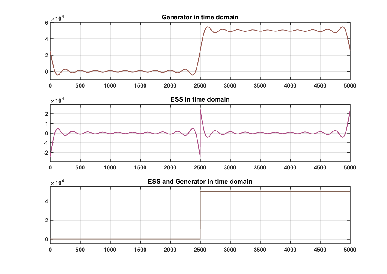
Figure 9: Step load with (20 sample cutoff)
Inversely, in figure 10 with a high cutoff (1000 samples) the genset is allocated to supply almost all of the energy to recreate the step load. This would be impossible because the genset cannot operate at such high frequency. A lower cutoff frequency must be chosen.
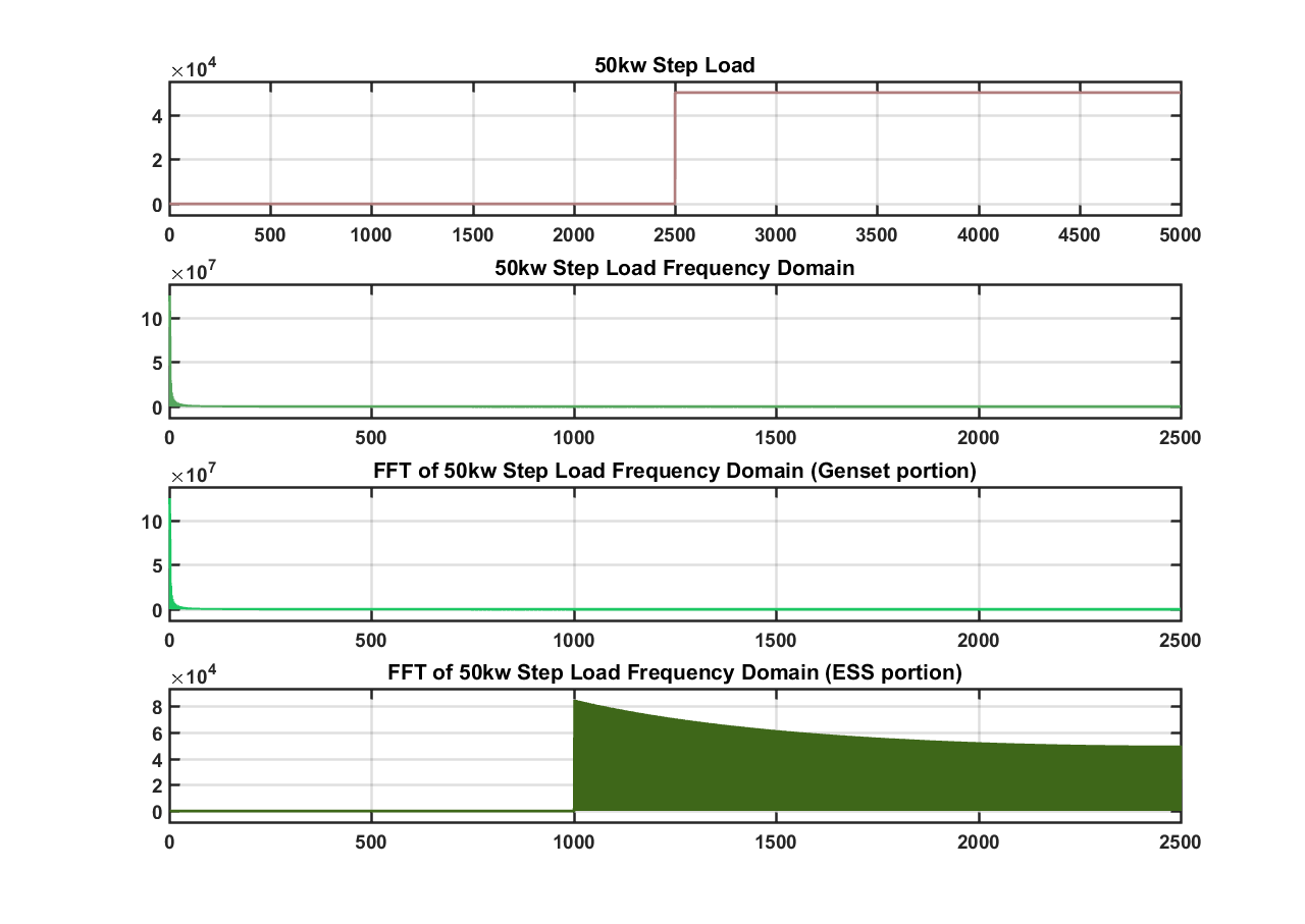
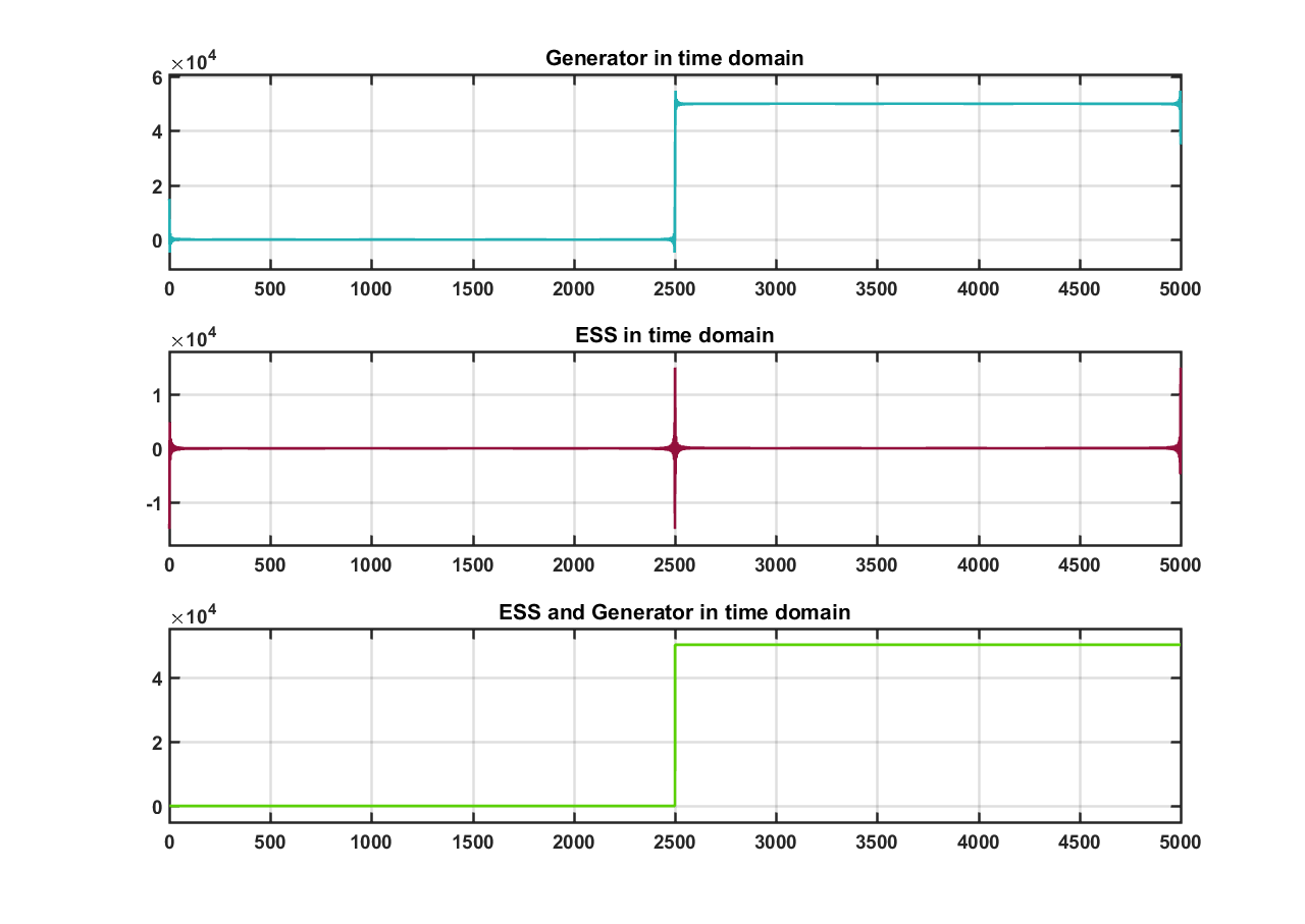
Figure 10: Step load with (1000 sample cutoff)
In figures 11 and 12 below, a dynamic load profile is used and the cutoff frequency is chosen at 20 samples and 1000 samples respectively. In the first case after the power allocation the genset curve is smooth. This would indicate the power allocation of the genset is correct because it may be able to handle this scenario. The ESS would then take the rest of the power allocation to achieve the step load.
In the second case, this again shows a cutoff frequency that is chosen to be to high. The genset would not be able to handle this scenario.
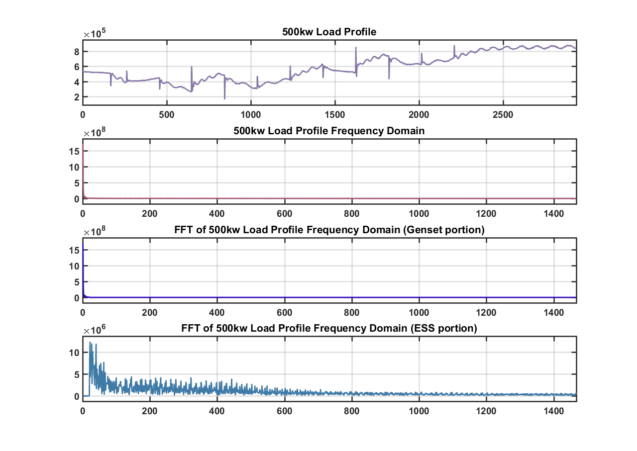
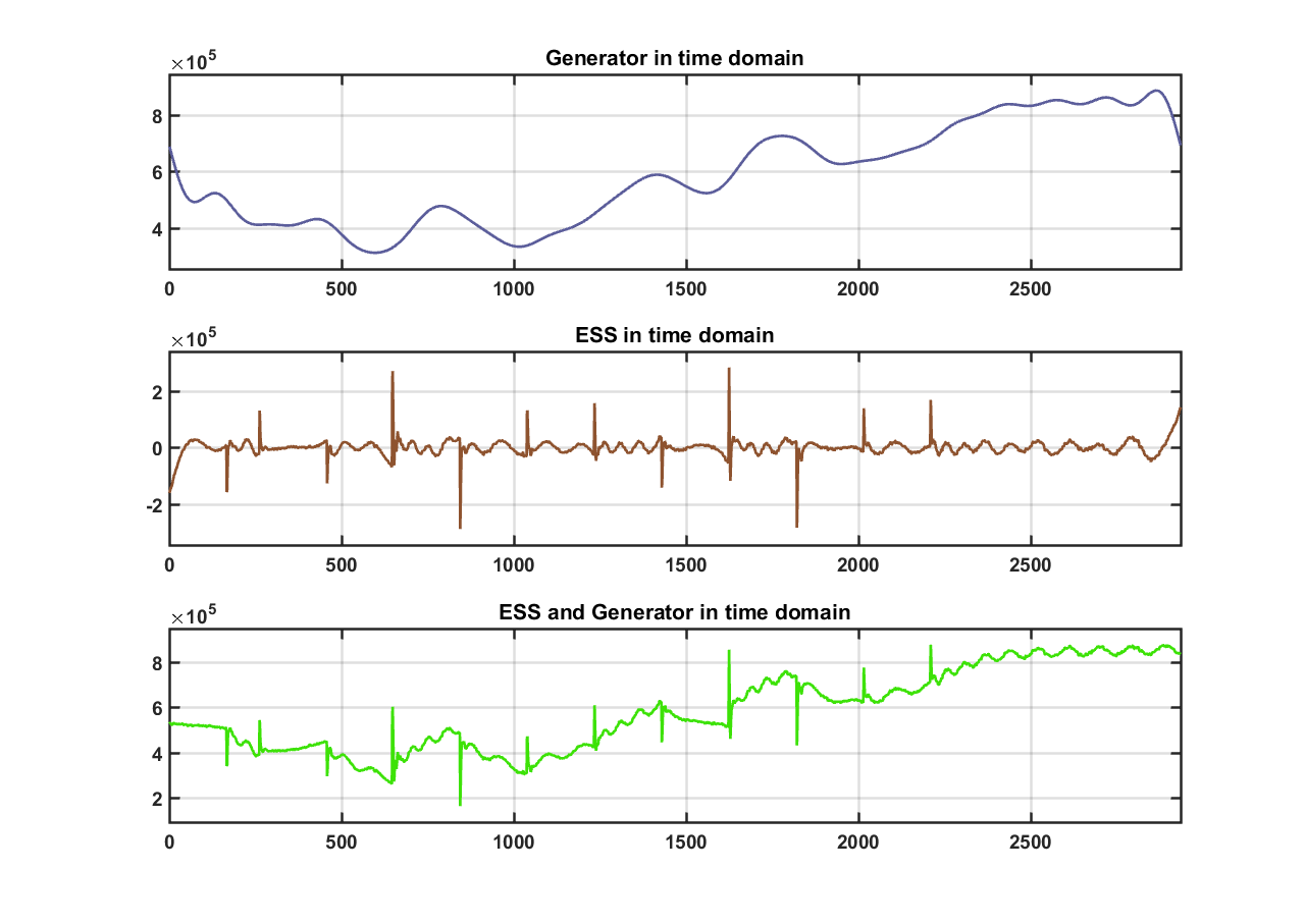
Figure 11: Dynamic load with (20 sample cutoff)
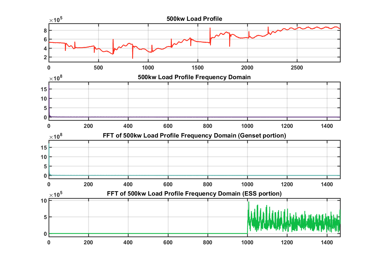
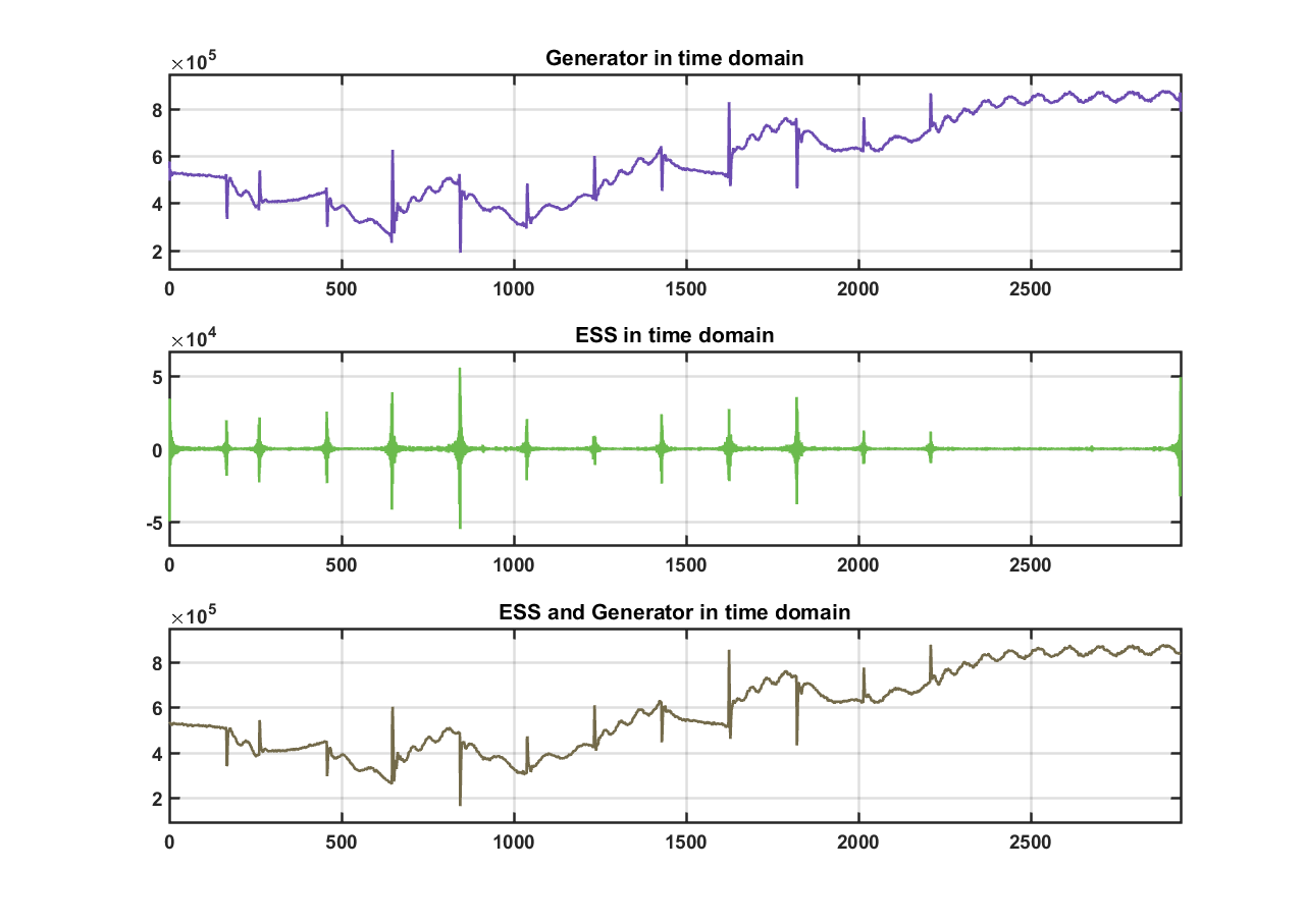
Figure 12: Dynamic load with (1000 sample cutoff)
Moving forward with this method, we think that finding an optimal cutoff frequency is critical. Currently we were choosing the cutoff based on our basic knowledge that a generator can only handle low frequency jumps. Our next step is to find out if there is a specific cutoff frequency that is recommended for our genset. If we can’t find this frequency, then we might have to identify a ramp rate for the generator using simulation data.
7. Simulations and Evaluations
The method of finding the power distribution between the ESS and the genset using the DFT will likely be the best approach to be used in solving the ESS sizing problem based on evidence from research. In [5], it is stated that this approach is more appealing because it uses less time and computational resources to arrive at an optimal solution to the sizing problem. Other important methods such particle swarm and genetic algorithms rely on either a random search or a technique similar to genetic reproduction respectively. The speed is an obvious concern because in some cases, it may take much longer to converge than would be reasonable for dealers or Caterpillar engineers. To validate results of the method we will run tests on the simulink model (high level of model can be seen below in figure 13). After results are confirmed to be correct on the simulink model, tests can be run at the TDI facility on a physical microgrid.
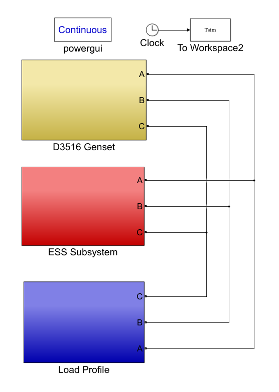
Figure 13: High Level Diagram of Simulink Model
8. Timeline and Work Division
In figure 14 below, a Gantt chart for the overall project timeline is given. Each section that has team written on it will be divided into smaller subtasks once they are determined.
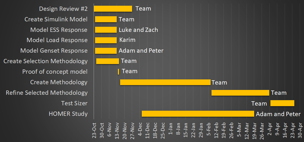
Figure 14: Gantt Chart
9. References
[1] Myles, Paul, Joe Miller, Steven Knudsen, and Tom Grabowski. “430.01.03 Electric
Power System Asset Optimization”. Morgantown, WV: National Energy Technology
Laboratory, 2011.
[2] “Distributed Energy Resources // ,” EPRI | Distributed Energy Resources. [Online]. Available: http://www2.epri.com/Our-Work/Pages/Distributed-Electricity-Resources.aspx. [Accessed: 29-Oct-2017].
[3]“Getting Started With SpecSizer,” Login. [Online]. Available: https://specsizer.cat.com/Help/Help.aspx?hcid=72. [Accessed: 21-Sep-2017]
[4] “HOMER Pro Version 3.7 User Manual”, HOMER Energy, Boulder, Co, 2016, pp. 9
[5] J. Xiao, L. Bai, F. Li, H. Liang and C. Wang, "Sizing of Energy Storage and Diesel Generators in an Isolated Microgrid Using Discrete Fourier Transform (DFT)," in IEEE Transactions on Sustainable Energy, vol. 5, no. 3, pp. 907-916, July 2014.
doi: 10.1109/TSTE.2014.2312328
URL: http://ieeexplore.ieee.org/stamp/stamp.jsp?tp=&arnumber=6787107&isnumber=6837545
[6] P. Li, D. Xu, Z. Zhou, W. J. Lee and B. Zhao, "Stochastic Optimal Operation of Microgrid Based on Chaotic Binary Particle Swarm Optimization," in IEEE Transactions on Smart Grid, vol. 7, no. 1, pp. 66-73, Jan. 2016.
doi: 10.1109/TSG.2015.2431072
URL: http://ieeexplore.ieee.org/stamp/stamp.jsp?tp=&arnumber=7112181&isnumber=7361791
[7] L. Zhang and D. G. Dorrell, “Genetic Algorithm based optimal component sizing for an electric vehicle,” in IECON 2013 - 39th Annual Conference of the IEEE Industrial Electronics Society, 2013, pp. 7331–7336.
[8] Mathworks.com. (2017). Simplified Model of a Small Scale Micro-Grid - MATLAB & Simulink - MathWorks United Kingdom. [online] Available at: https://www.mathworks.com/help/physmod/sps/examples/simplified-model-of-a-small-scale-micro-grid.html [Accessed 4 Oct. 2017].
[9] Ramachandra Rao Kolluri, Julian de Hoog, Khalid Abdulla,
Iven Mareels, Tansu Alpcan, Marcus Brazil, and Doreen Anne Thomas, ”Siting and Sizing Distributed Storage for Microgrid Applications”