Range-Finding Rear-Collision Accident Prediction and Warning For Motorcycles with Integrated Signal Vest
The LED grid was not made, but the LED strand used to model the grid provided enough results for a conclusion. It was decided that the best balance between the number of LED's and the power consumed is about 70 LED's. This makes a 7X10 grid of LED's, which can be used to display the basic signals needed. The LED strip is also bright enough to be used in both daytime and nighttime applications.
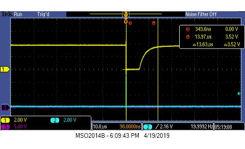
The full sensor was not completed during the project, but the APD/TIA circuit was able to display a received signal from the laser diode and showed a difference in time of flight with a distance change of less than two meters. The specific accuracy of the sensor cannot be determined based off of the results received, but it can be shown that the system is working well enough to discern distance.
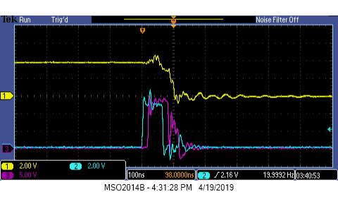
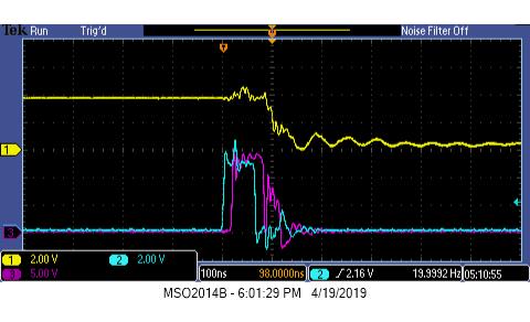
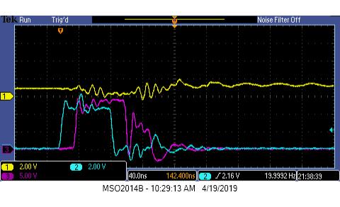
Figure 4 and 5 show the output of the TIA in yellow, the start pulse from the MCU in blue, and the laser start pulse in purple. Figure 4 shows the received signal at no distance, while figure 5 shows the received signal at two meters. The good news is that between the measurements, it can be seen that there is a time delay. For figure 4, the starts to drop off immediately after the large "M" bounce of the signal. Figure 5 shows the signal start to drop off a short while after the large "M" bounce. The bad news is how noisy the signals are. Disconnected from the rest of the circuit, the blue signal is a perfect square wave output from an MCU. Once connected to the circuit, there is an issue that dirties the signal. It is assumed to be the MOSFET driver's shunting diodes speed capabilities that distort all the signals in play. It is also the explanation for why the purple signal seems to be activated twice. Figure 6 below shows the full power of the distortion when the APD is overloaded with light.
The distortion is not he only problem. The received signal from the APD/TIA circuit last longer than the laser pulse that activates it. Figure 7 shows the signal restoration over time. The capacitance of the APD continues to push current through the circuit long after the signal has ended. This can limit the speed that the system can take measurements and slow down the accident prediction reaction time.