Range-Finding Rear-Collision Accident Prediction and Warning For Motorcycles with Integrated Signal Vest
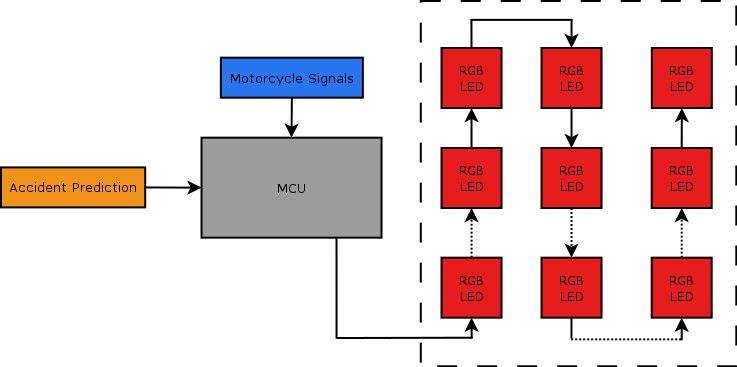
The LED display was modeled by a pre-fabricated string of 72 SK6812 individually addressable RGB LED's. This model was then used to test the library developed for the SK6812. This library has to be developed in such a way as to program the LED's and be able to handle an interruption in the data. The library has to be flexible enough to handle a varying amount of LED's in the string. For the grid of LED's itself, a serpentine pattern was chosen to reduce the amount of connections needed between the LED's. This pattern is shown in figure X below. To handle the SK6812 library and program the LED's, Atmel's ATTiny 2313A was chosen. This MCU can run at 16MHz and can handle all of the input output signals needed. The rest of the design for this subsystem, including the design of the interface between the MCU and the motorcycle's signals, is left for implementation.
The sensor is broken into many parts. There is the sending side of the sensor, which is taken care of via a laser diode and accompanying circuitry. The receiving side of the sensor is an avalanche photodiode and accompanying circuitry. There is also a chip that handles timing of the light pulses flight, and a micro-controller that will convert the time into a distance. Once the distance has been calculated, the distance will be sent to the central MCU to be used in accident prediction.
The sending side of the sensor is meant to send out a pulse of light to the object in its path. The light will then reflect off of it and return to the sensor. The light to be sent out is a 905nm wavelength pulse of less than 100ns in time. Generating this light is a component called a laser diode, which works like any other light emitting diode except for the direction of light. In normal LED's, the light is emitted in all directions. For the laser diode, the light is emitted in a single direction creating a laser. The laser diode chosen for this is OSRAM Opto Semiconductors Hybrid Pulsed Laser Diode with Integrated Driver Stage SPL LL90_3. This laser has a peak power output of 70W and can therefor supply the powerful light signal needed to travel the maximum of 200m (100m to target and 100m back) required. There is a power MOSFET switch internal to the diode that allows for an external device to turn on and off the laser [3]. This means that an MCU can control the laser as needed. During the development of the sensor, it was discovered that the internal MOSFET requires more impulse current than an MCU can deliver to turn charge the gate terminal of the MOSFET enough to let it turn the laser on. For this reason, a MOSFET driver was needed. Fortunately, there is an application note that describes what part to get and how to apply it to the laser diode [4]. The MOSFET driver used is Renesas' EL7104 high-speed single channel power MOSFET driver. This driver responds to the input signal fast enough to not worry about the delay and provides the amount of power required to activate the laser diodes internal MOSFET. The driver receives a signal from the MCU and turns on the laser, which sends a pulse of light into the world.
The receiving side of the sensor receives the pulse of light after it has bounced off of the target and come back to the sensor. The receiver for the sensor is an avalanche photodiode (APD). The APD allows current to flow through once it has received light. The avalanche photodiode chosen for this task is Marktech Optoelectronics MTAPD-06-009 905nm APD. This APD is designed for automotive applications and is able to receive a signal from 200m away [5]. The problem with an APD being the receiving side of the sensor is that, being a diode, the APD controls current. MCU's cannot use a change in current as a change in logic. MCU's are voltage devices. There needs to be an intermediary component that convers the current into a useable voltage. There are many methods to perform this action, but the best design available is a transimpedence amplifier (TIA), also known as a current to voltage converter. The design of the TIA is the most involved design of the project. TIA's are normally fairly simple; a bipolar reference supply with low frequency signal changes make for an easy environment. Unfortunately, in this application the environment is not as forgiving. The op amp at the center of the design needs to be able to work off of unipolar reference since the motorcycle battery cannot provide a negative voltage. The op amp must also be a rail-to-rail op amp in order to allow the output to reach the needed voltages. Due to the speed of the incoming signal (on the order of ns) the op amp must also have a high-speed response. During the building and testing of this portion of the project, it was also discovered that there must be a small voltage on the positive terminal of the op amp in order to charge the terminal and allow the op amp to operate. To meet these requirements, TI's OPA380 precision high-speed transimpedance amplifier is used [6]. After this circuit was put together, the system did not work. The reason traces back to the APD being used. With a low reverse voltage bias, the APD has a higher capacitance. Starting off with a 5V reverse bias made a large capacitance that could not be charged all the way with the short light pulse. In order to fix this issue, a reverse bias of 60V was applied. This reduced the internal capacitance to a workable amount and the receive circuit worked.
In order to measure the amount of time that the light pulse is in the air, a Time-to-Digital IC is used. This chip is functionally a stopwatch that communicates over SPI. The TI TDC7200 works for the application because it has 55ps resolution, can measure from 12ns to 8ms, and can average multiple times [7]. The clock starts when a start pulse is received and stops with a stop pulse. The MCU sends a start pulse at the same time it activates the laser diode, and the APD/TIA converts the received light pulse to a stop pulse and ends the clock. The TDC7200 then prepares a data packet to be sent over SPI communications. The issue with the TDC7200 is that it is a 3.3V part. The rest of the logic for the project works at 5V. This means that the communication between the TDC7200 and the MCU must be level shifted. Normally, taking a 5V signal and dropping it to 3.3V is a simple process. A voltage divider can simply reduce the voltage to the required strength. The issue comes into play with the timing of the system. Since the data needs to be transferred quickly so a measurement can be obtained, the voltage divider and its several us delay does not fit the requirements. The problem is brought back up when looking at the 3.3V conversion to 5V. In order to solve the timing and voltage issue, high-speed comparators are required. For this project, TI's TL714C high-speed differential comparator is used. This part has a response time of 6ns; compared to the 5-20us response time of the voltage divider, this is the best option [8]. Once data can be transferred between the MCU and the TDC7200, the only other hardware is the 1uf capacitor required by the datasheet on the VREG pin.
The MCU for this portion of the project has to bee fast enough to work with the TDC7200, and have the bit capabilities to handle the math required to convert the data from the TDC7200 to time and then distance. To ensure that all of these parameters are achieved, Atmel's ATMega 1284 MCU is used. This MCU can be ran at 20MHz, has enough ram storage to handle the calculations, and supports SPI, (the communication standard used by the TDC7200). For the MCU, the firmware had to be set up as master to receive data from the TDC7200 and send data to the central MCU. The firmware also had to be designed to work on a schedule so distance measurements are taken at the correct times. Due to time limitations, the project was unable to reach this stage.
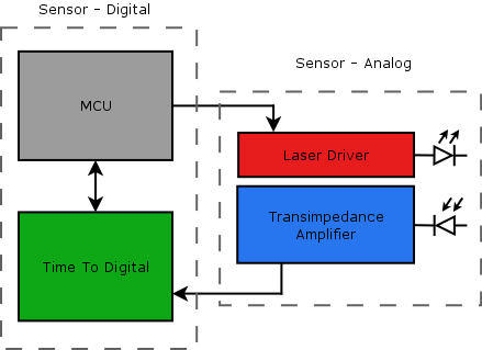
This figure shows the high level connections between components in the sensor system. To reiterate, the way the sensor system works is that the MCU determines that a distance measurement is needed and sends a start pulse to the time to digital chip and the MOSFET driver. This starts the timer and sends a pulse of light into the world. The light then bounces off the target and returns to the APD. The transimpedance amplifier converts the APD's analog signal into a digital one and stops the time to digital chip's counter. The time to digital chip then sends the time of flight to the MCU. The MCU then uses the data to determine the distance between the motorcycle and the following vehicle. This information is then sent to the central MCU (refer to figure 1) to perform the accident prediction.
The portion not talked about thus far is how the system is going to be powered. Motorcycles have 12V batteries that power the engine, ECM, displays, and lights. This 12V battery is unstable, meaning that the output can be anywhere from 9V to 15V. Both the sensor and the LED display will receive power from the battery. In order to convert the unstable 12V into useable 5V and 3.3V logic, a power regulation system must be used. It would be inefficient to use a power dissipater (a chip that simple burns off the extra voltage as heat) to convert potentially 15V to 3.3V. To retain efficiency, a switching power converter is used. TI's LM22678 step-down voltage regulator is used to complete this task. The L22678 is designed for automotive applications, i.e. stepping a car, truck, or motorcycle battery down to logic levels. This chip can provide up to 5A of current for the circuit needed and has internal power cutoff for when the system reaches too high of a temperature. In order to differentiate between a 5V output and a 3.3V output, the feedback pin is connected to a voltage divider that balances the output to the required voltage [10]. This chip is more than able to handle the stresses of the project.
As the project came to a close, more power requirements were found. The laser needs to have a 15V input to generate a strong enough light pulse to travel the full range and return off of a diffuse target. Since the motorcycle battery supply’s 12V, a step up power conversion will need to be used. The second power requirement discovered is the APD's reverse bias. To eliminate capacitance, a 70V reverse bias is required. When using a step up power converter for this, the power consumption will need to be taken into account. These are the extra power issues needed.