Range-Finding Rear-Collision Accident Prediction and Warning For Motorcycles with Integrated Signal Vest
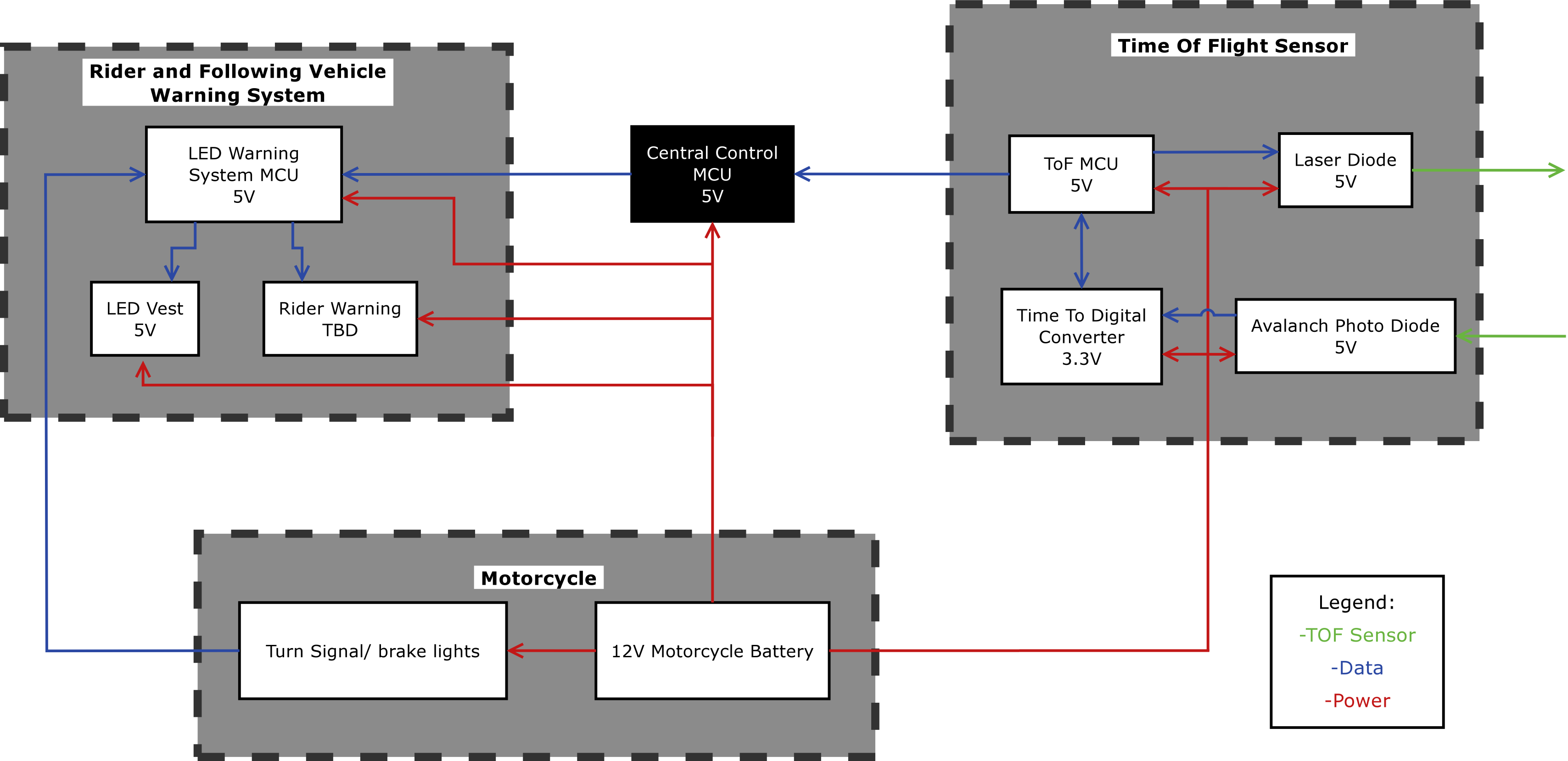
Over all, the plan for the project is to eventually be implemented in industry. Motorcycles, and most modern vehicles, have a computer on board called the Engine Control Module (ECM). This computer handles all of the electronic components and processes on the vehicle. Everything from vehicle monitoring to the engine warm up process is controlled and regulated by the ECM. With the ECM's functionality in mind, the subsystems of the project were designed to take input from a central "intelligence". Figure 1 shows the project block diagram. The black box in the center shows a "Central" micro-controller (MCU), which controls the sensor and the warning system. Another parameter focused on during design is cost. As mentioned before, if the system costs too much, customers will not purchase the motorcycle. For this reason, part selection variables included price.
The LED display is not a hardware heavy project. In fact, the choice to use individually addressable LED's limited the hardware selection down to two options. The SK6812 individually addressable RGB LED by Adafruit was the best choice as its LED's have quicker programming times than the competition. Beyond this, the rest of the hardware in the display subsystem is a micro-controller that programs the LED grid. This micro-controller needs to be fast enough to program the LED's and receive signals from the central MCU. Though not focused on in this project, the LED display has other parameters it must follow. The display is to be mountable to the motorcyclists' jacket, backpack, and rear trunk. Since the display is to receive its power and data from the motorcycle, it must have a breakable connection should the rider be in an accident. If the rider is in an accident, having a tether to the bike could cause more damage to the rider since the rider can't get away from the falling bike. The LED grid itself can only consume about 2A of current (10W of power) to ensure that the motorcycle's battery is not depleted.
The sensor has a long list of requirements. The sensor must be able to detect up to 100m away with 5cm of accuracy. The 100m range was chosen for a worst case scenario, a semi-truck at 60 mph in the rain while the motorcycle is stopped. This range will give the truck enough time to come to a complete stop once they see the warning from the display portion of the project. The 5cm accuracy was chosen based off of the maximum amount of time it takes to receive a reading then process the data, and how much a vehicle would have moved in that time. If the vehicle moves less than the resolution of the sensor can detect, than the sensor will not be able to tell that the car has moved, thus making the system useless. With that, the system must be able to make a measurement in less than 25ms. This time was chosen so that the system will be able to take multiple snippets of information, make calculations based on the received data and send data to a central system. Other vehicles may use sensors that emit the same sensor signal, so the project system will need to be able to tell which received signal is from its own sensor. The project is loosely based off of LIDAR systems, so it is known that the ToF sensor will work in all light and weather conditions. On the side of processing, the MCU must be fast enough to receive the data and convert the time to distance and send it to the central MCU.