Since 2013, Bradley University’s Department of Electrical & Computer Engineering has competed annually in the International RoboBoat Competition. This competition requires teams to create an autonomous boat designed to complete challenges. These challenges involve tasks such as obstacle detection and avoidance of objects such as buoys and shoreline.
Historically, the Bradley RoboBoat team has struggled to determine objects’ distance relative to their boat. To determine distances of objects, past Bradley projects have used a camera. This method has proved ineffective as camera images do not contain depth; distances must be approximated using geometric techniques.
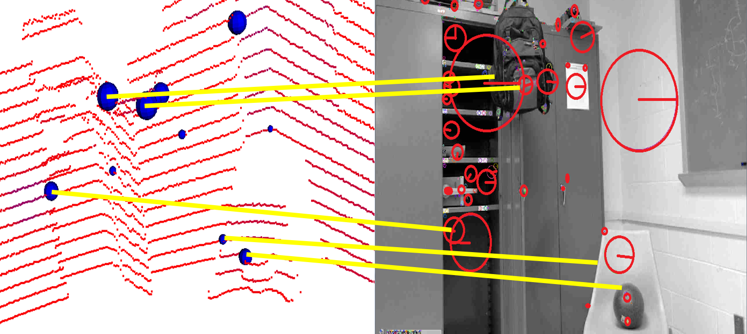
Lidar is a viable method that can provide distance measurements to the RoboBoat. Lidar is a method in which a laser is emitted from a laser scanner. These beams of light are reflected off of surrounding objects, received by the scanner, and then interpreted to determine the distance to these objects. Lidar technology is already used in a variety of environmental mapping applications in the autonomous vehicle industry.
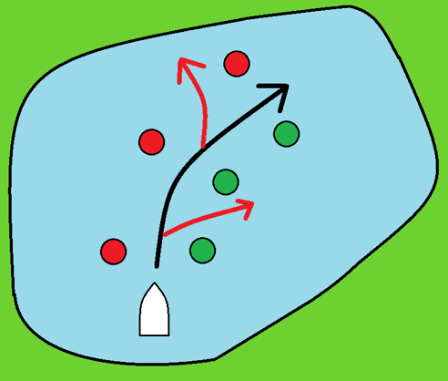
Distance miscalculations lead the boat astray as shown in red.
Boat must pass between buoys as shown.
The Bradley RoboBoat project advisor desires a system that can be used to locate objects in front of the RoboBoat using accurate distance measurements. In addition to these raw distance measurements, images should be created that can clearly be interpreted by human users to determine depth in an image of the surrounding environment. Implementation of such a system requires three main components. First, a laser scanner will be used to measure the distance to surrounding objects by utilizing lidar. This lidar device will be used for the scanning and modeling of the surrounding environment in three dimensions. Second, a camera will be programmed to take still images. Lastly, an embedded device will communicate between the laser scanner and camera and process the incoming data. Furthermore, though not integral to the measurement system, a hard drive will be used for data storage. This storage will be helpful for postrun testing.
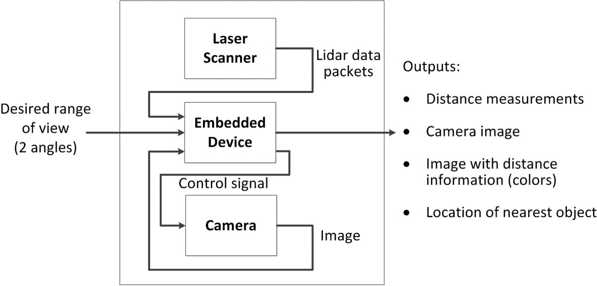
To ensure that this system performs as desired, certain performance goals should be considered. First, registration of camera images and lidar data must be flawless to create accurate images with implied depth. Both the camera and the laser scanner will need to communicate with the embedded device. Similarly, the system must communicate with the existing electronic components typically used by the RoboBoat team. Finally, as the boat is participating in a competition, data processing must be performed in real time due to the time constraints imposed by the competition.