AC System Monitoring Device
Photo Gallery
Fall 2015
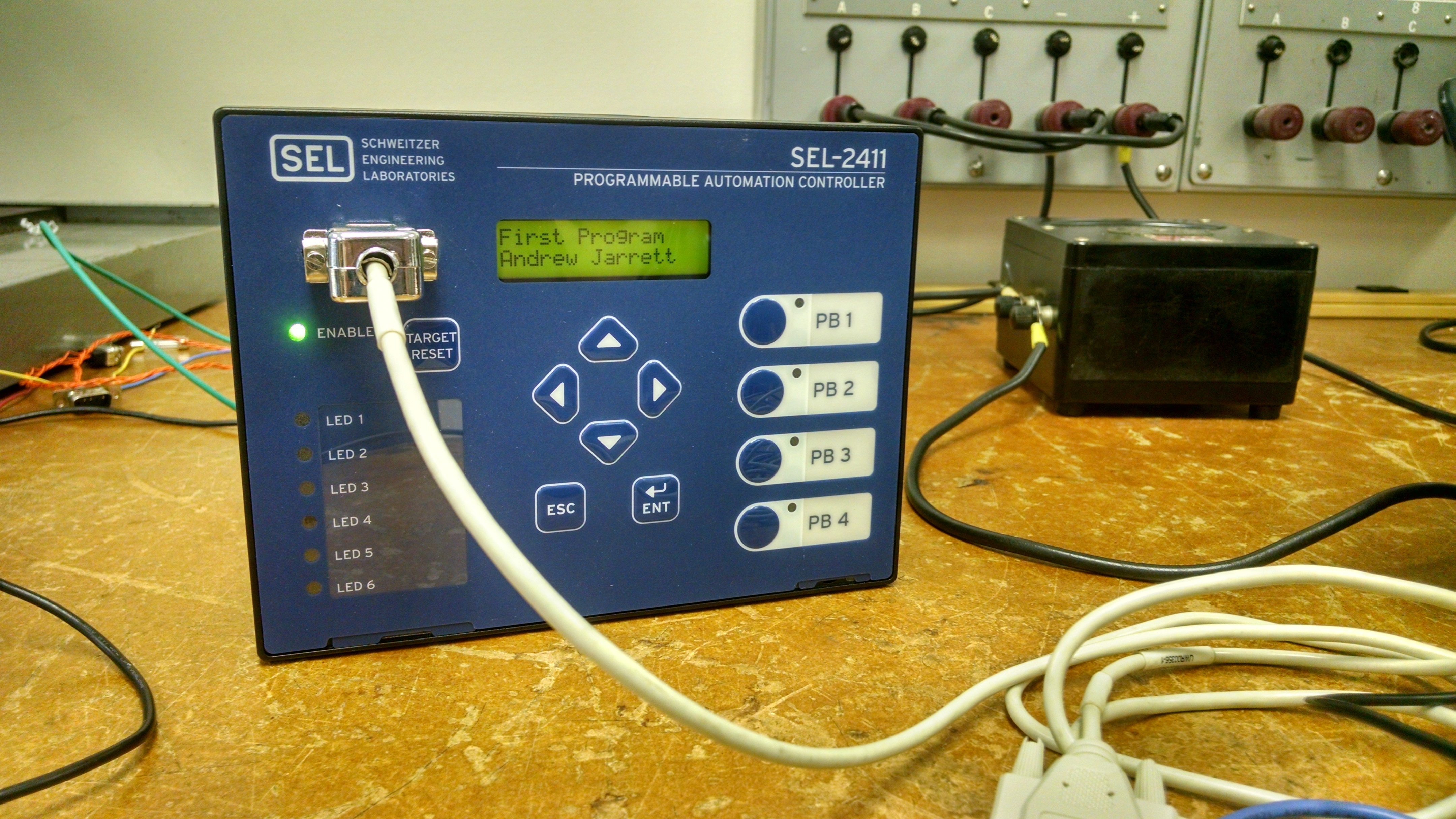
Fig. 1. Programming the SEL-2411 for the first time.
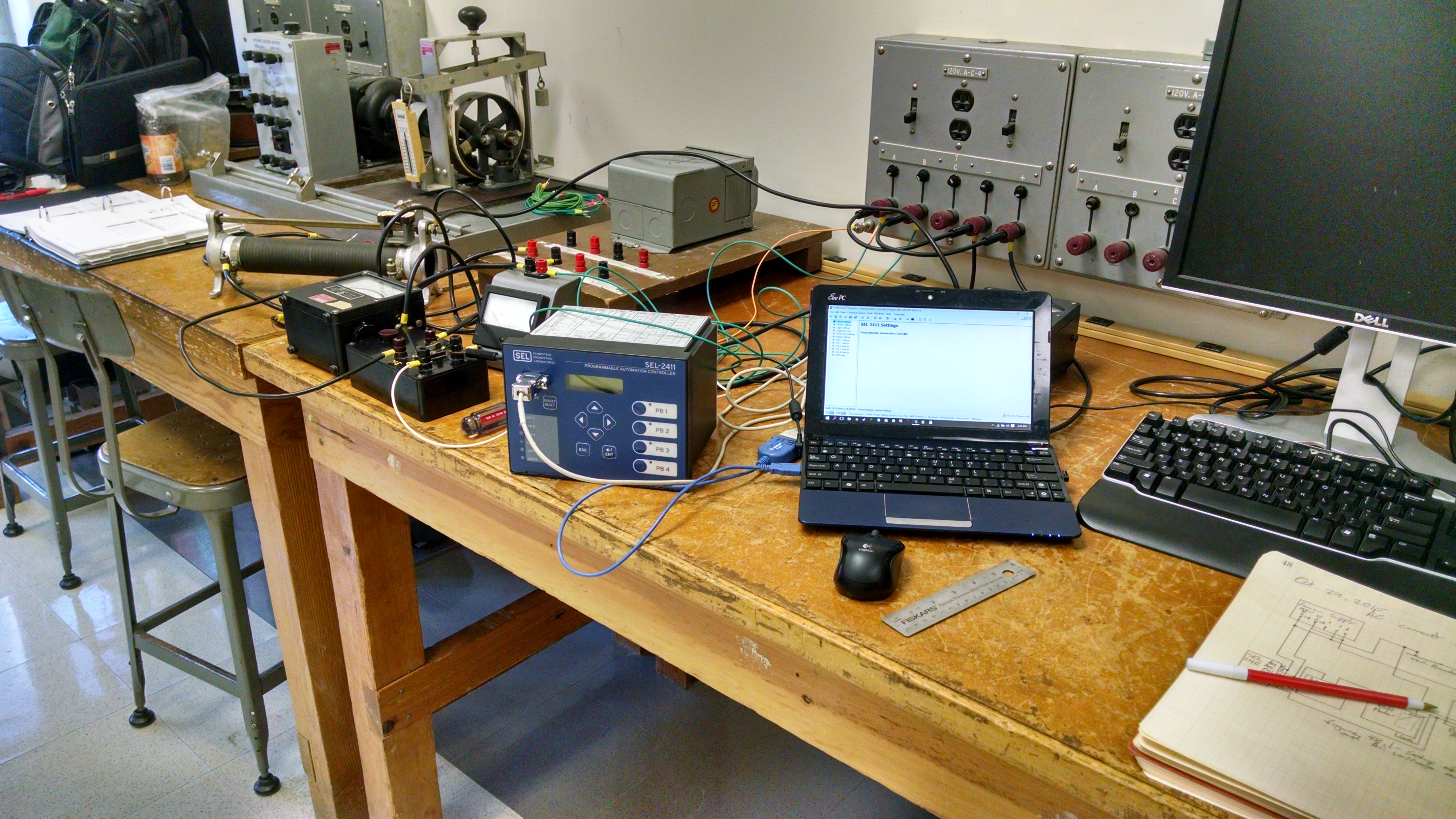
Fig. 2. Setting up first resistive and inductive load for current monitoring
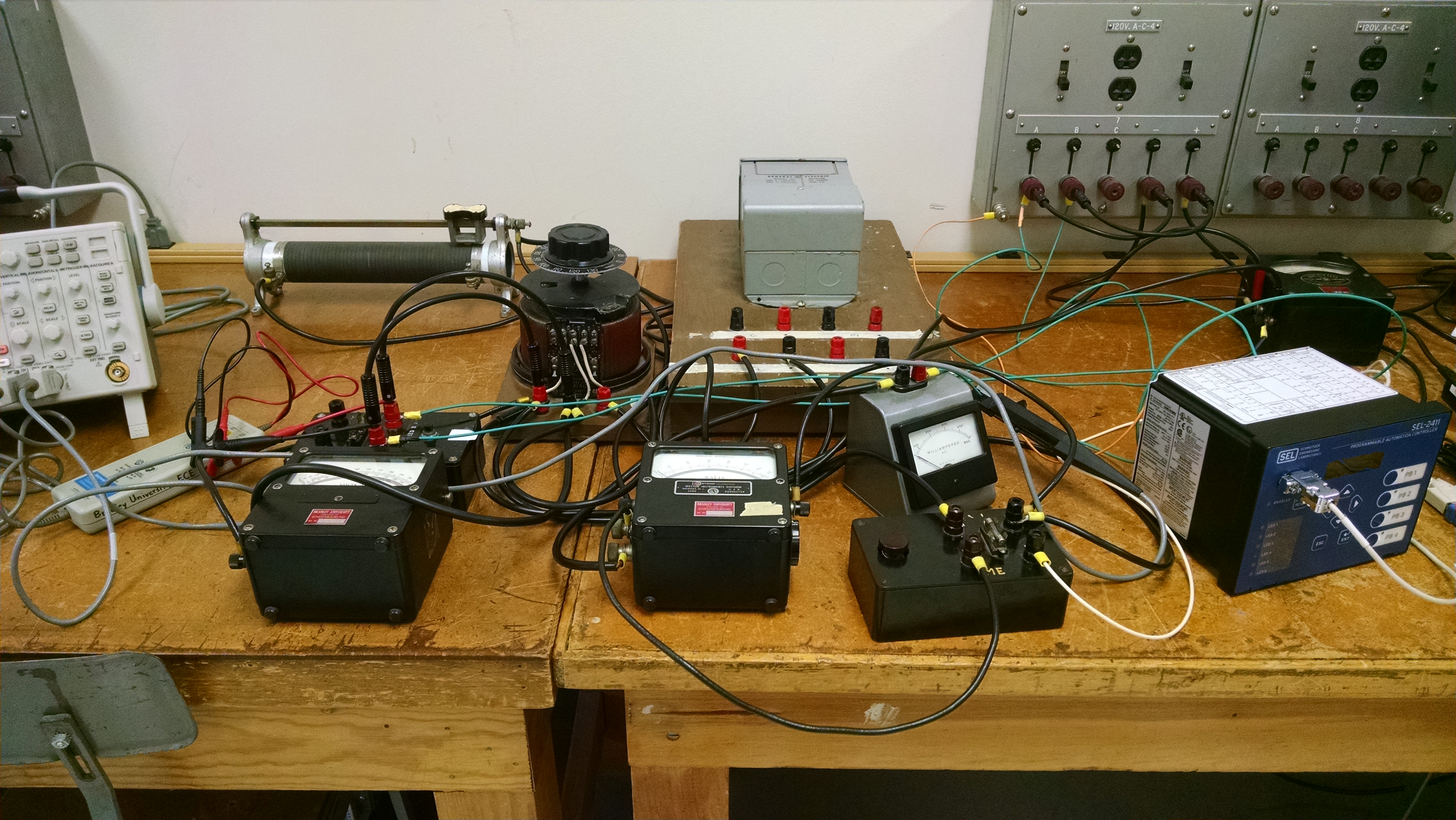
Fig. 3. Setting up additional circuitry for controlling voltage and current for testing
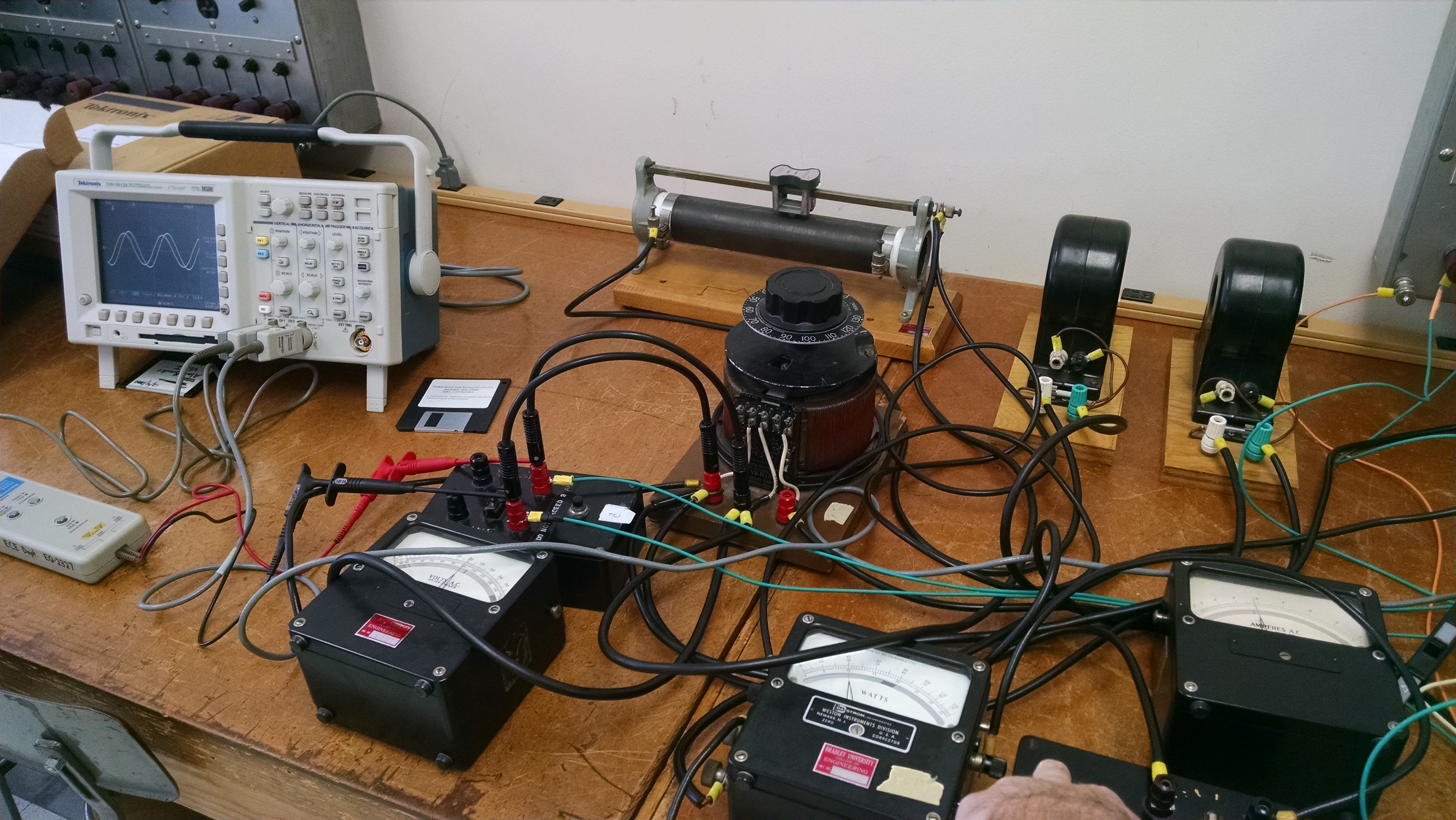
Fig. 4. Setting up new RL load with
177Ω Rheostat and loading reactors as transformer resulted in nonlinear relationships. Additional oscilloscope to view the waveforms of the AC voltage
and current.
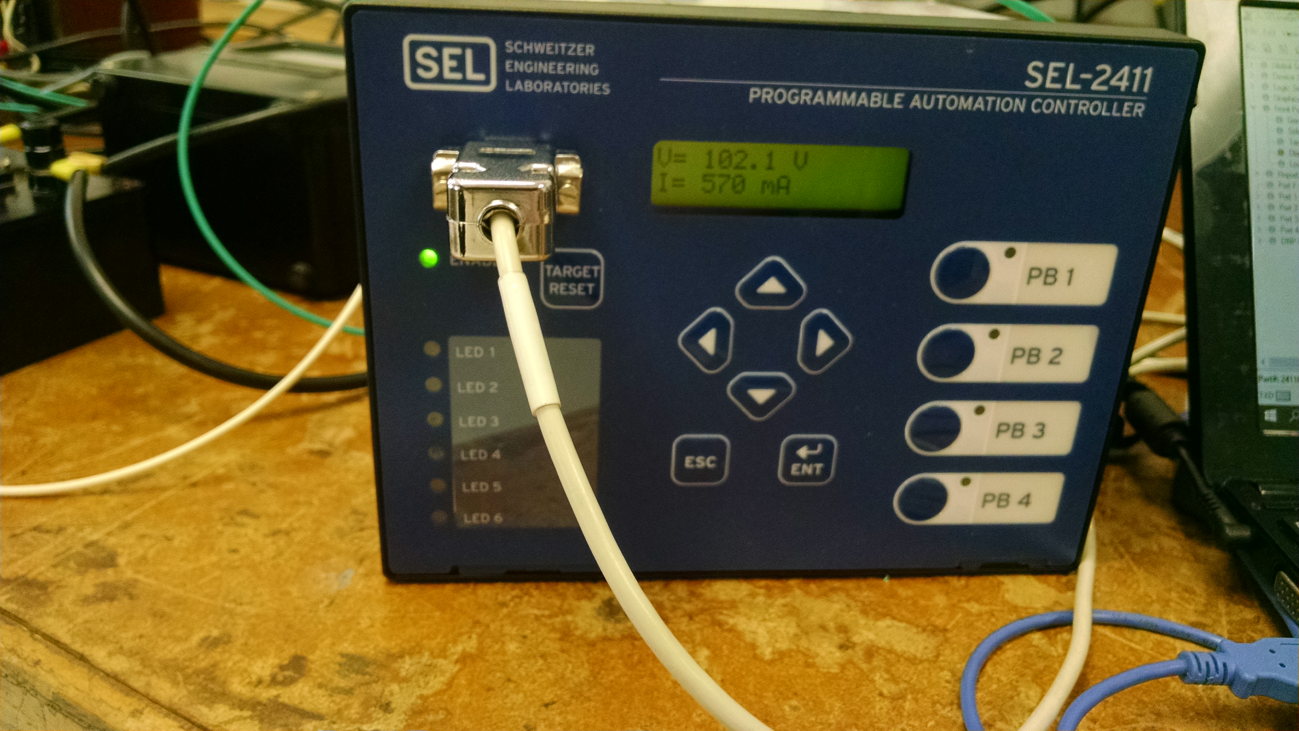
Fig. 5. Displaying AC voltage & current to the user on the SEL-2411 automation controller
Spring 2016
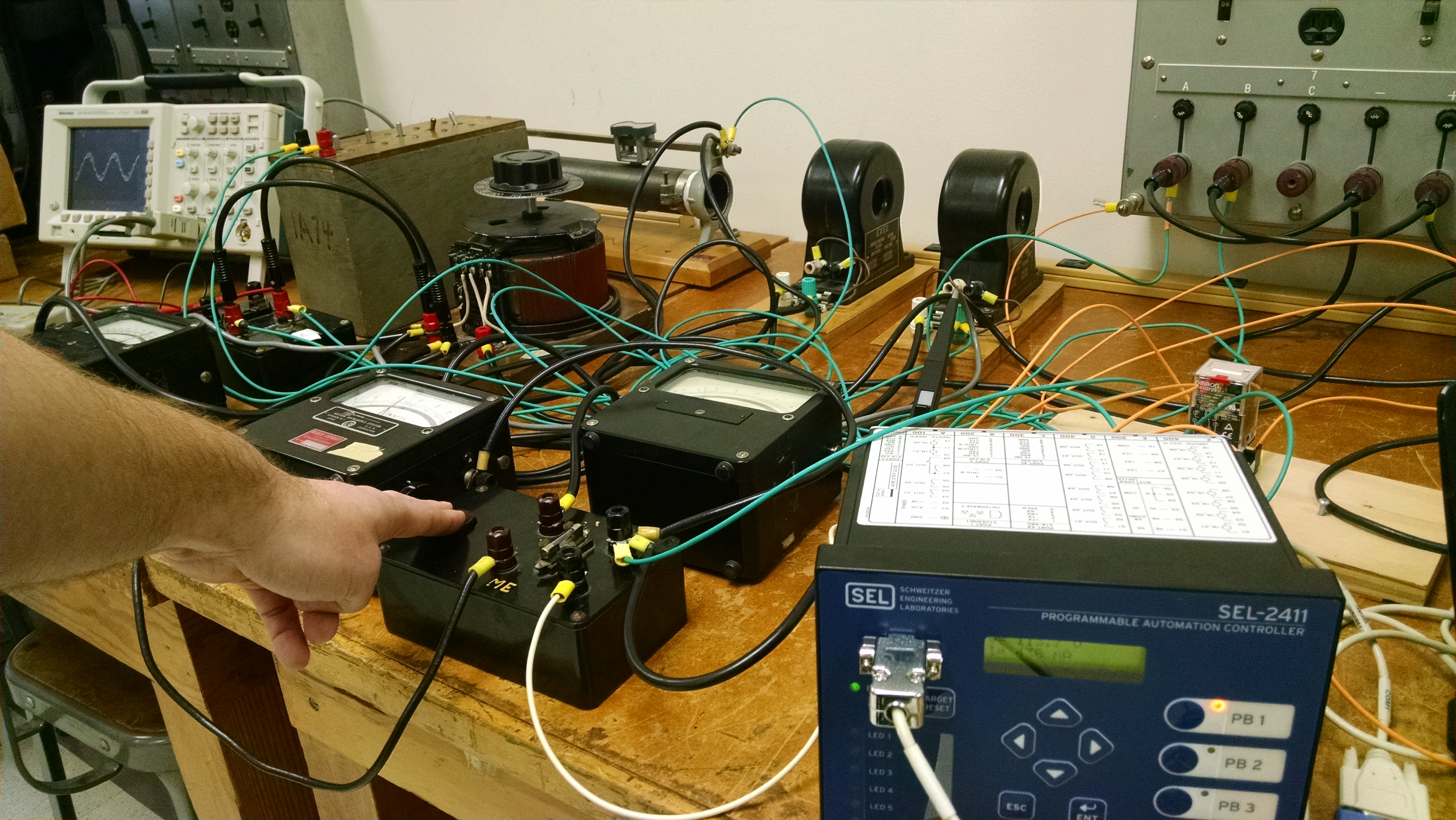
Fig. 6. Setting up power factor correction circuit utilizing a capacitor bank and relay control.
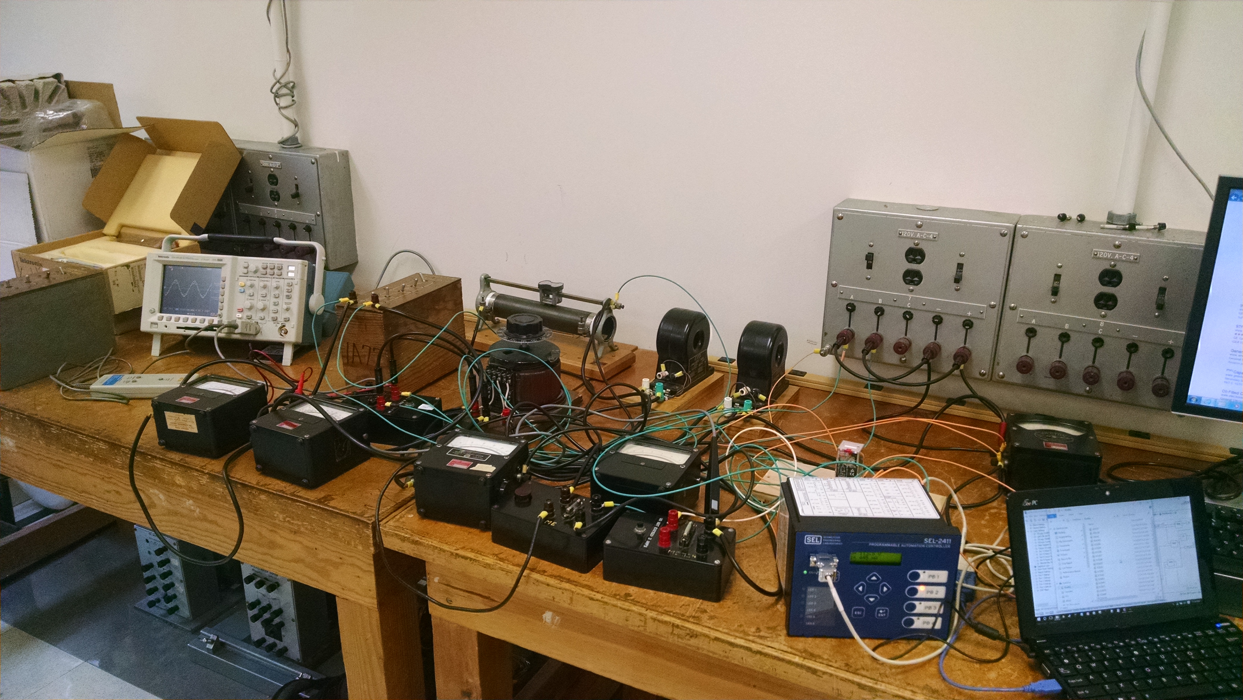
Fig. 7. Circuit setup of power factor correction control. Still troubleshooting with current distortion by power harmonics in the system.
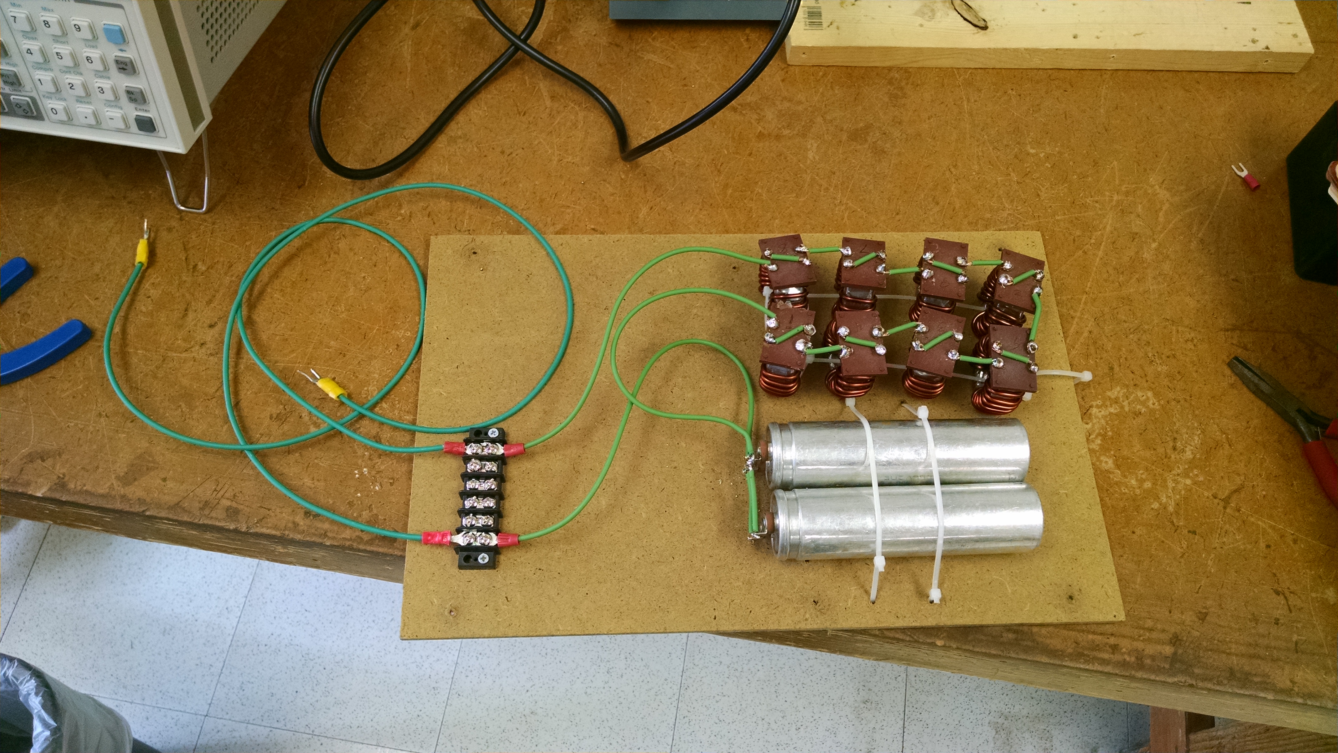
Fig. 8. Harmonic filter design to filter out the 7th Harmonic. This will be connected in parallel with the load.
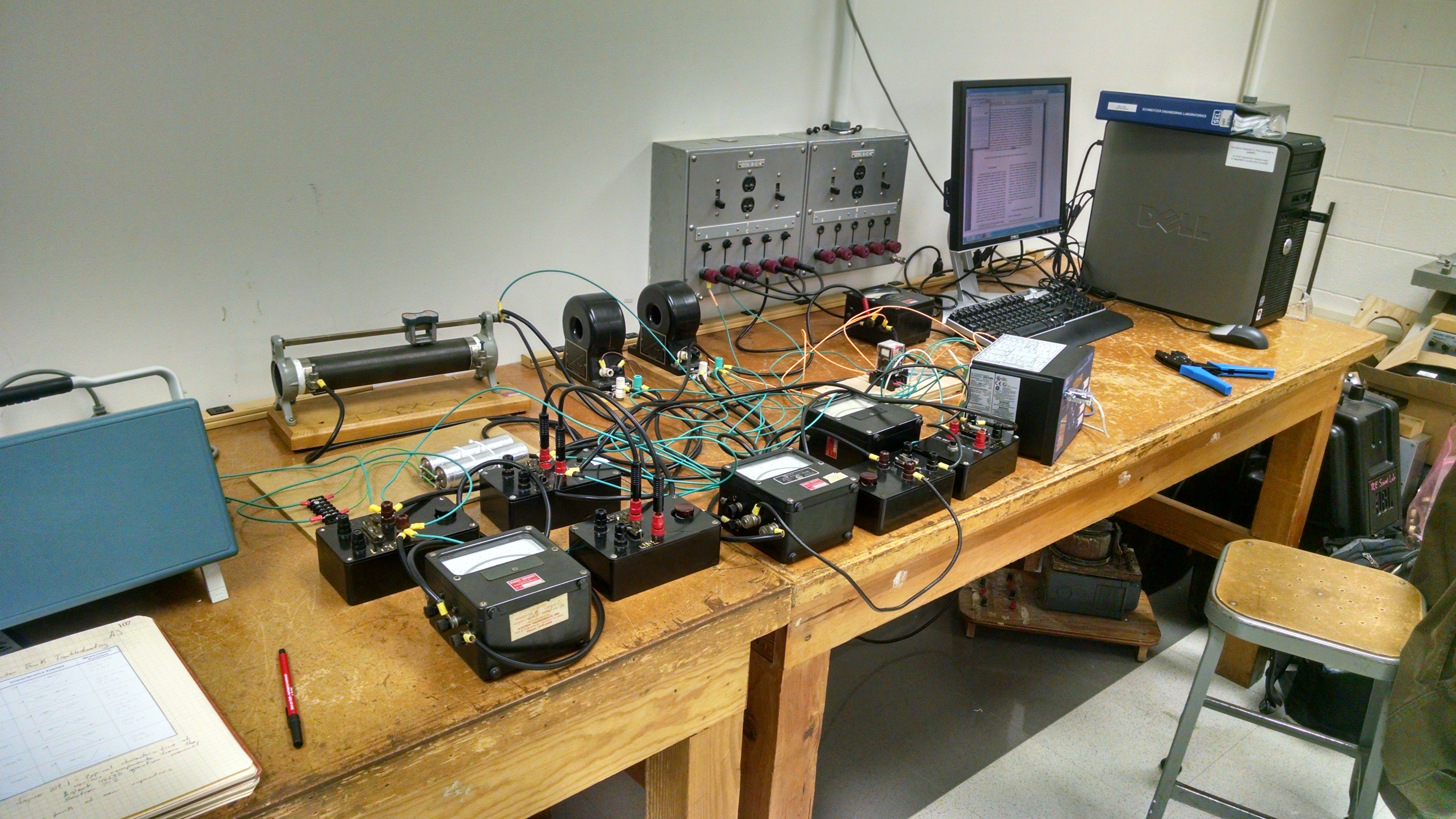
Fig. 9. Harmonic filter setup for the test bench to control the power factor of the RL Load.
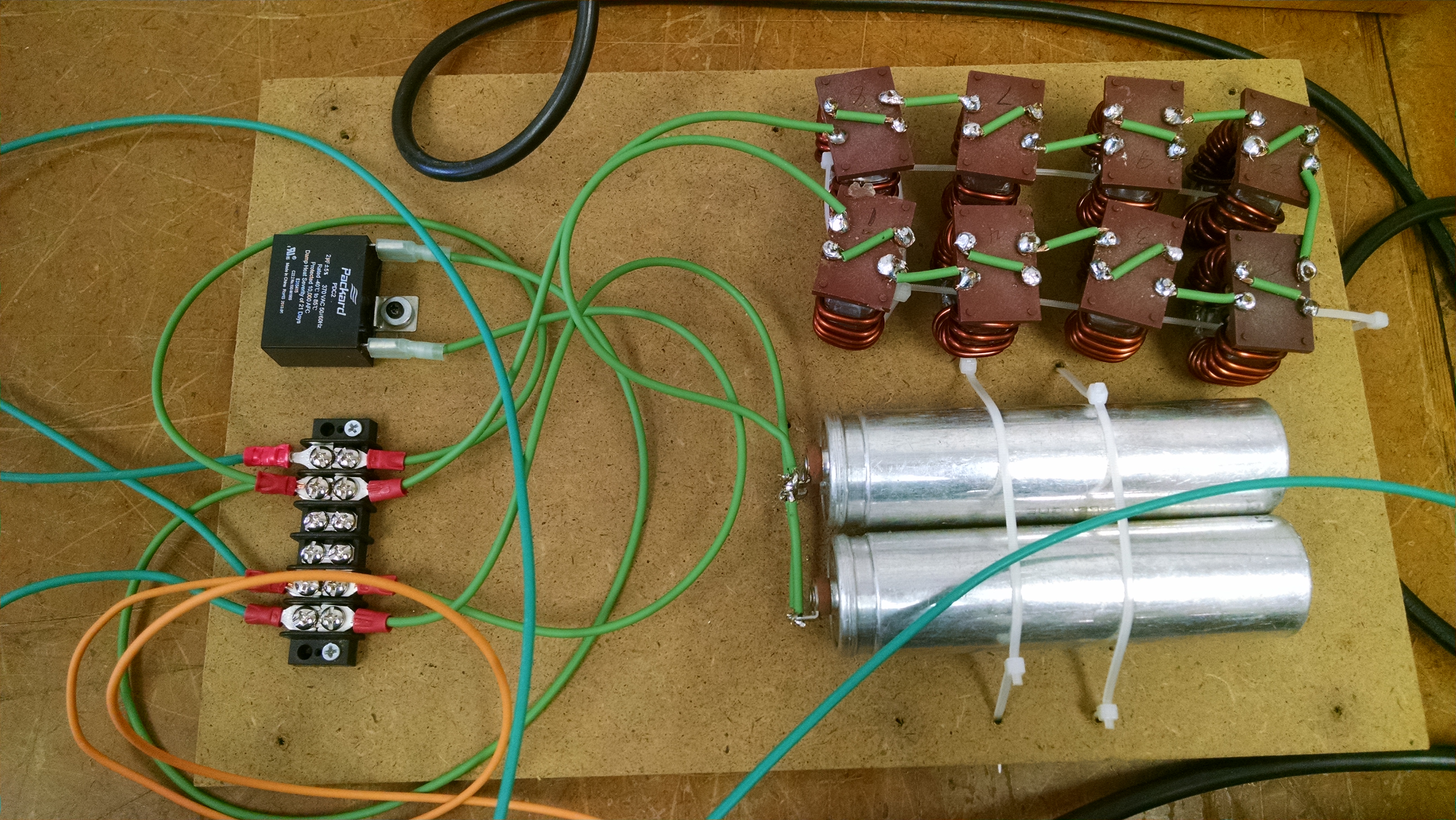
Fig. 10. Harmonic filter design build
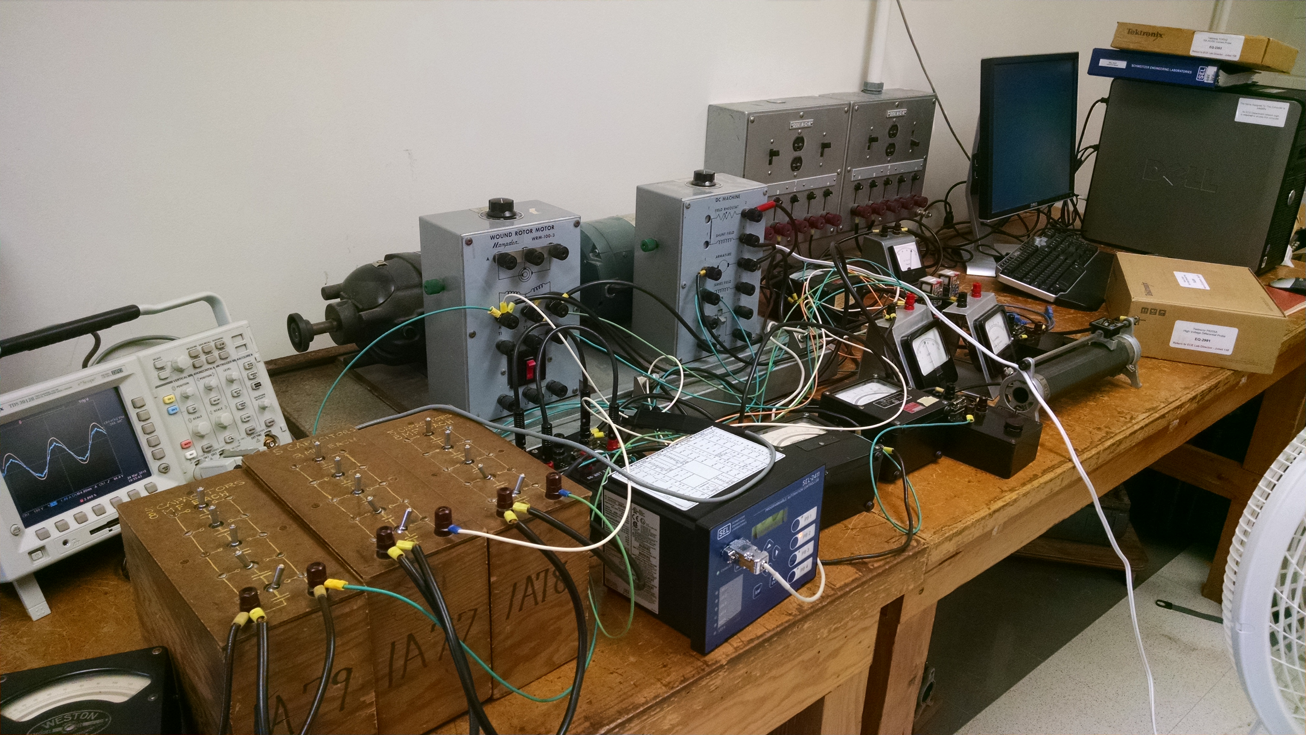
Fig. 11. Setup for three-phase power factor correction using DC motor to control the load torque on the three-phase motor. Harmonics on the three-phase power factor correction
are less prominent and harmonic filter was not needed.
Fig. 12. Front screen operations of the SEL-2411 Programmable Automation Controller