VARIABLE INPUT CONSTANT OUTPUT VOLTAGE REGULATOR
VARIABLE INPUT CONSTANT OUTPUT VOLTAGE REGULATOR
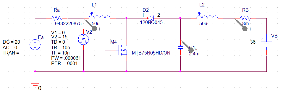
fig 1. Orcad Simulation having 20[V] Input
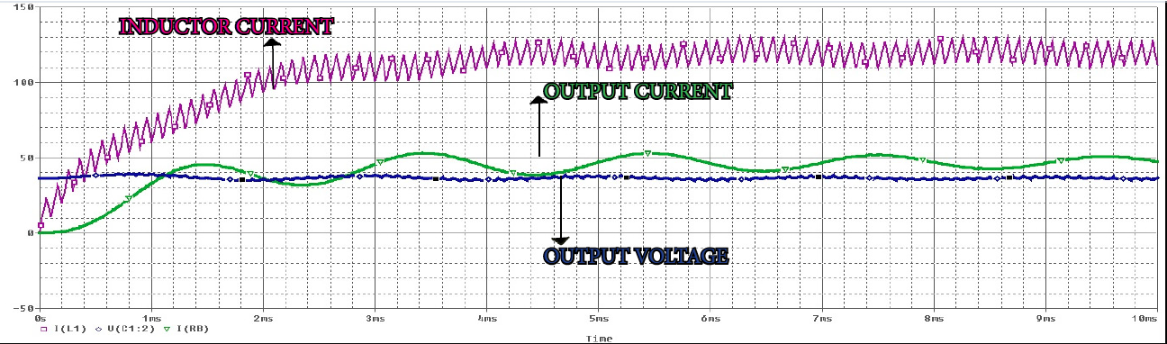
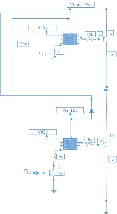
fig 3. The gate drive module used to turn on and off the IGBT.
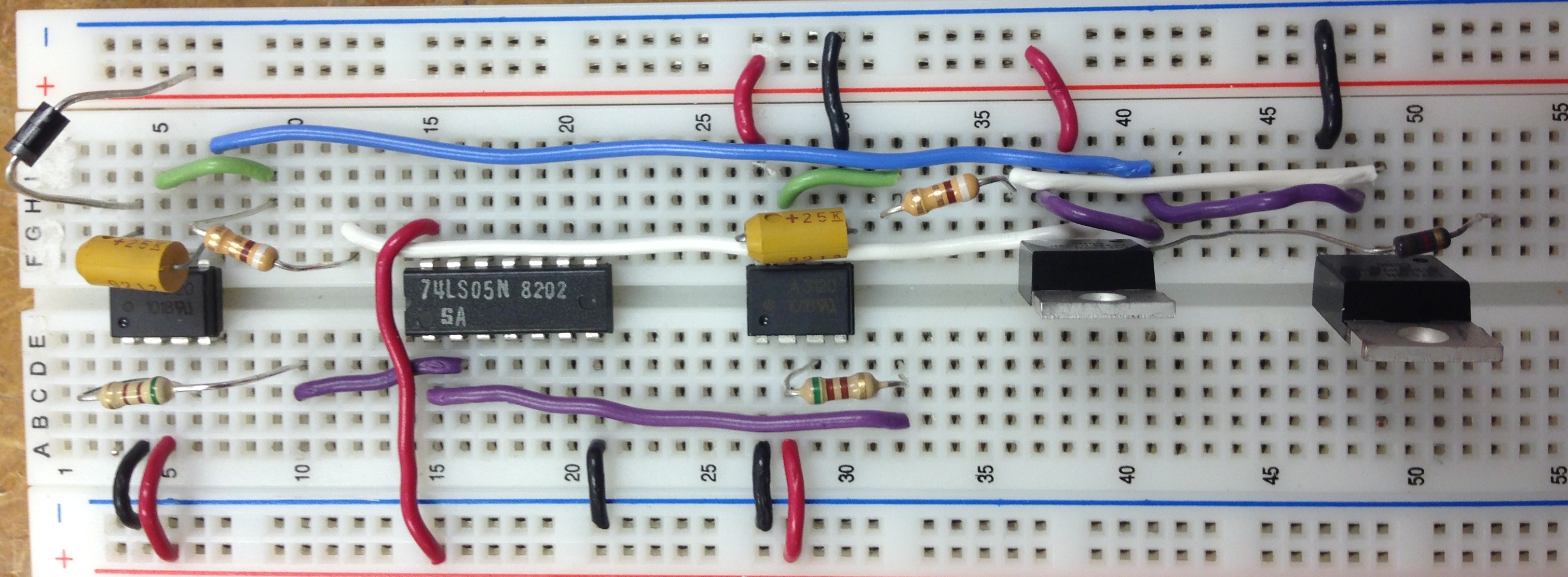
fig 4. The finalized gate drive module used to turn on and off the IGBT.
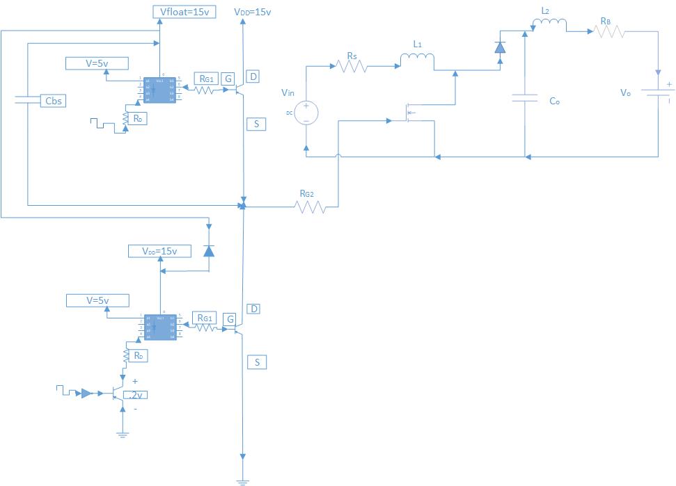
fig 5. The gate drive module and the boost converter merged.
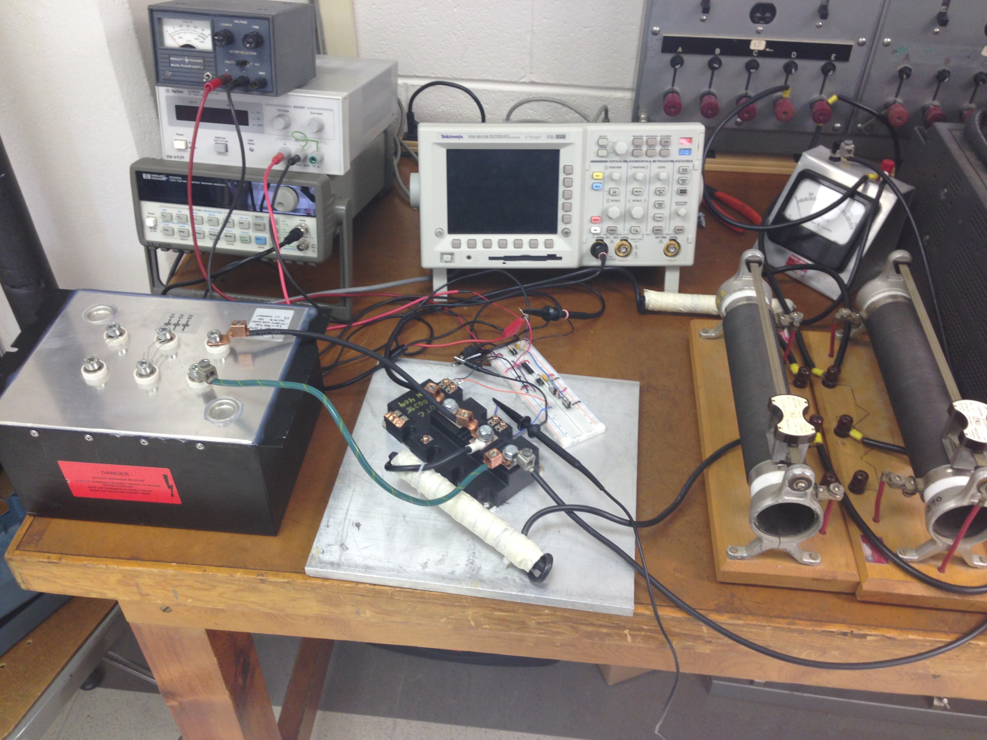
fig 6. The physical gate drive module and the boost converter merged.
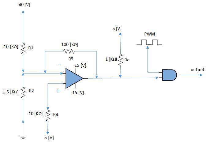
fig 7. The protection circuit design.
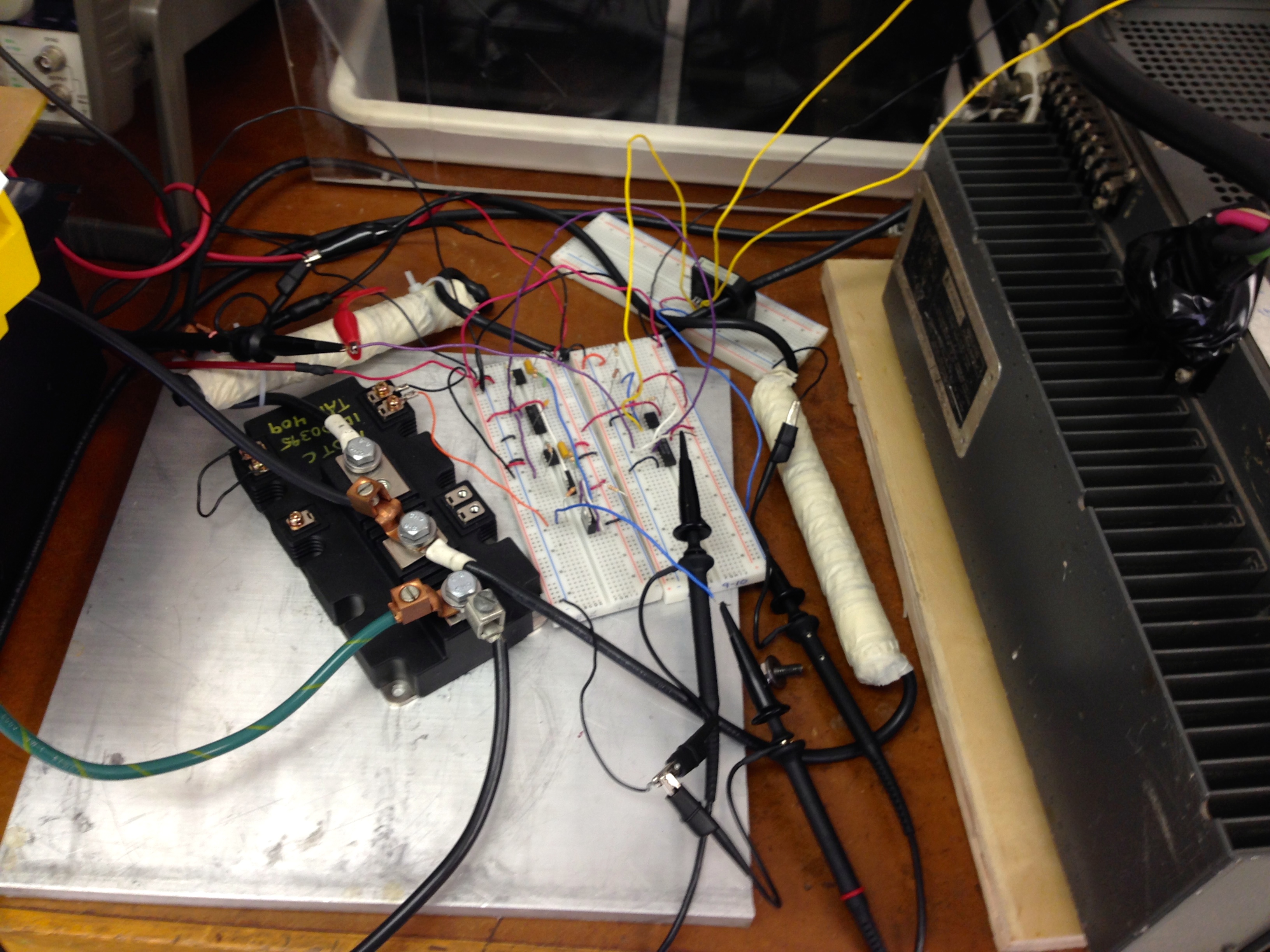
fig 8.The protection circuit implemented with the power electronics.
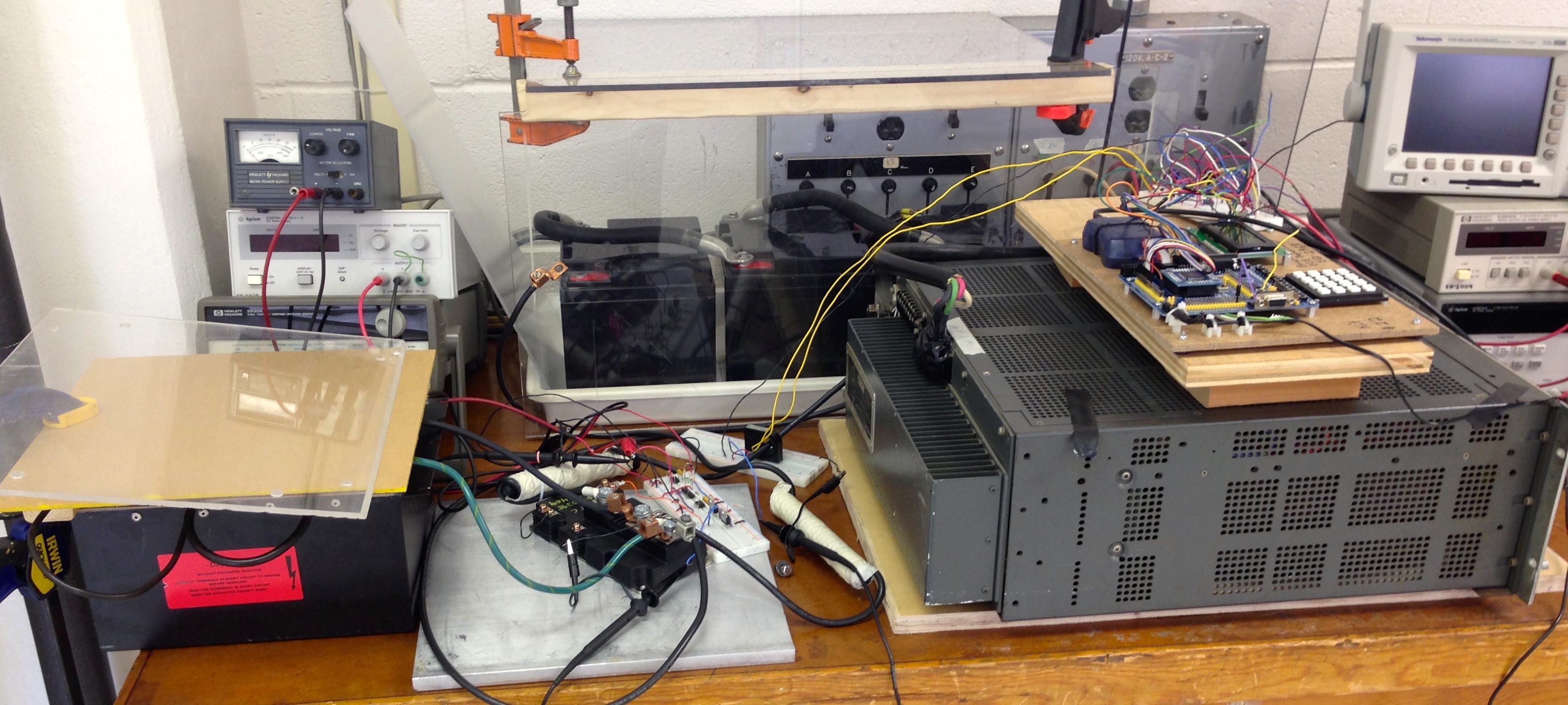
fig 9.The overall power electronics implemented with all added circuits.
connect with us