Simulation Results
Simulink is an extremely helpful simulation tool that allows for verification of a system’s operation without physically uploading it onto the FPGA board. After the phase-locked loop was implemented into the system, the complete QPSK system shown was downloaded to the FPGA board successfully. 14-bit high speed (up to 65M sample/second) digital-to-analog converter and analog-to-digital devices are used as the communication channel. When the I and Q channels of the received signal are combined in an x-y representation, they form the QPSK constellation grid. Without carrier synchronization, the QPSK constellation grid was not available; rather a rotating phasor was observed. The recovered constellation grid is shown in Fig. 6. The PLL tracks the carrier frequency offset and synchronizes the carrier frequencies successfully.
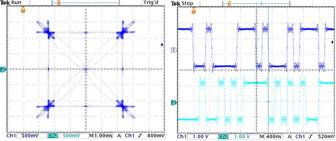
Fig. 6. Hardware implementation results shown on an Agilent oscilloscope. Left—QPSK constellation recovered after carrier synchronization. Right—I and Q channels at the receiver.
Once system operation is verified on the FPGA device, further simulation techniques are used to analyze the phase ambiguity condition of the system. Visual results are the desired approach, in order to verify and evaluate the design. The image shown in Fig. 7 is used for testing of the transmitter and receiver. In order to do so, image processing techniques are required to convert image data to a QPSK representation. After pre- and post-processing, transmission and recovery of the image can be completed. As seen in Fig. 7, a phase ambiguity of 180 degrees exists, resulting in the inversion of colors. An issue discovered during transmission is the shifting of the image. In Fig. 8, image (b) at the receiver is shifted down a number of rows. To this point, the reason for the shift has not been discovered and is under research.
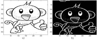
Fig. 7. Phase ambiguity in tested image. a) transmitted image. b) recovered image.
However, phase ambiguity of the system has been corrected for. This can be seen in Fig. 8 where no color distortion occurs. In order to preserve color features of the image, additional pre- and post-processing is required to convert the eight bit numbers of the red-green-blue map to a binary representation and then, a QPSK representation. As can be seen in image (b) the shifting of the image still exists.
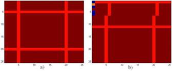
Fig. 8. 8-bit color preservation test after phase ambiguity correction. a) transmitted image. b) recovered image.