Phase-locked Loop
The synchronization
of the carrier frequencies is the most important piece of the
communication system. In a wireless communication channel, various
channel imperfections like ISI and Rayleigh fading due to multi-path
effect exist. Without a synchronized local oscillator, data cannot
be extracted correctly from the received QPSK signal. Implementing a
phase-locked loop (PLL) is a standard method used to regenerate
carrier frequency and correct for the channel imperfections
introduced during transmission.
The QPSK waveform carries phase information that represents data.
By performing the following computation
![]() (2)
(2)
where
Δϕ denotes the phase
error, X(n) and Y(n) are the outputs from decimators.
I(n) and Q(n) are the in-phase and
quadrature hard-decoded data.
The phase error (Δϕ) in Fig. 1 is calculated and then used to adjust the
frequency and phase of the local oscillator. As the error is reduced
to zero, the transmitter and receiver frequencies become
synchronized, allowing for extraction of data from the
I and Q channels.
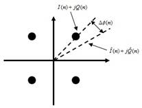
Fig. 1. QPSK constellation grid.
Equation (2) is calculated for every data sample, meaning that this must be implemented in hardware and run at the symbol rate. The phase error calculation is illustrated in Fig. 5. This rapid calculation is occurring in the “Carrier Recovery” block of the system block diagram, and serves as a feedback controller for the adjustment of the local oscillator.
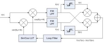
Fig. 5. Phase-locked loop.
Crucial
to the design of the PLL is the loop filter, which provides direct
control over the PLL bandwidth. The bandwidth of a PLL is the
measure of the PLL’s ability to track the input clock and jitter. A
high bandwidth provides a fast lock time and tracks jitter on the
reference clock source, passing it through to the PLL output,
whereas a low bandwidth filters out reference clock jitter, but
increases lock time [4].
To control phase error, proportional and integral (PI)
control techniques are used via a loop filter. PI control is
implemented by selecting values for Kp and Ki, which provide the user with control over bandwidth and
a damping factor. By optimizing these parameters, the system can
achieve carrier synchronization with both a fast locking time and
reduced jitter. First, the bandwidth for desired operation is chosen
and then Kp and
Ki values are derived using the following
equations.
![]() (3)
(3)
![]() (4)
(4)
where θ=2π*BW and BW is the bandwidth.