Phase Ambiguity
Every M-ary PSK
system suffers from a condition called phase ambiguity, which is due
to the nonlinear operation performed on the signal for carrier
regeneration. The PLL
locks onto a wrong phase and this incorrect locking characteristic
introduces a static phase rotation. In QPSK systems, phase ambiguity
occurs at any multiple of 90 degrees. This is to say that when the
PLL “locks” onto the signal at the receiver, the symbol previously
located in the first quadrant at the transmitter may now be located
in a different quadrant at the receiver. The phase error exhibited
in this symbol will also exist for every other symbol.
Taking a look at the effect of phase ambiguity in QPSK systems, it
is apparent that each channel (I or Q) exhibits one of two different
states and both channels combine for a total of four different
states as seen by the constellation grid. The state of each channel
may be either a replica of the transmitted signal or an inverted
signal. Fig. 3 shows the I channel at both the transmitter and the
receiver. The signal is inverted which will result in either a 90 or
180 degree phase ambiguity as seen in Fig. 4. If the Q channel has
no inversion, the symbol will be seen in quadrant two with a 90
degree phase ambiguity, whereas if the Q channel is inverted, a 180
degree phase ambiguity will exist and the symbol will be located in
the third quadrant.
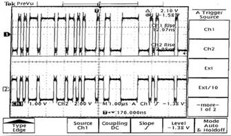
Fig. 3. Phase ambiguity in the I channel of a QPSK signal. The top plot represents the signal at the transmitter and the bottom plot, the signal at the receiver.
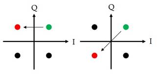
Fig. 4. Phase ambiguity possibilities for the signal in Fig. 3.
This phase ambiguity must be corrected for proper decoding of data. In order to do so, a differential coding scheme can be implemented into the system, which transmits the difference between two consecutive symbols of data rather than each symbol separately. By doing so, phase ambiguity is resolved by differencing the phases of two symbols.