Media Gallery
Pictures, videos, and other media related to our project can be found here.
Photo Gallery
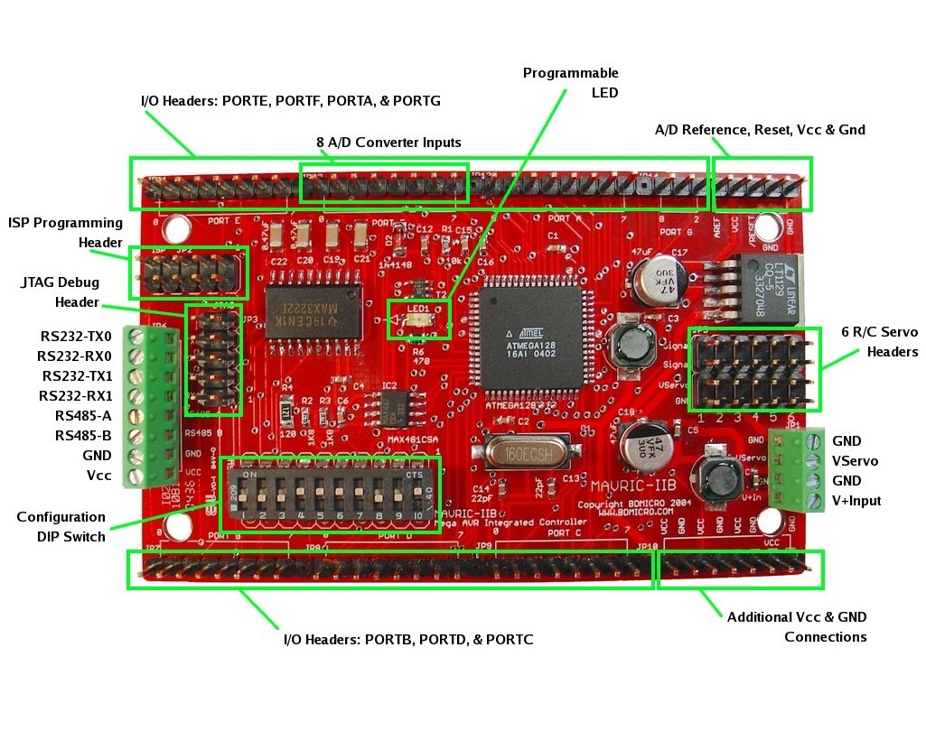
↑ The BDMICRO MAVRIC-IIB is a powerful microcontroller board based on
the ATmega128 MCU.
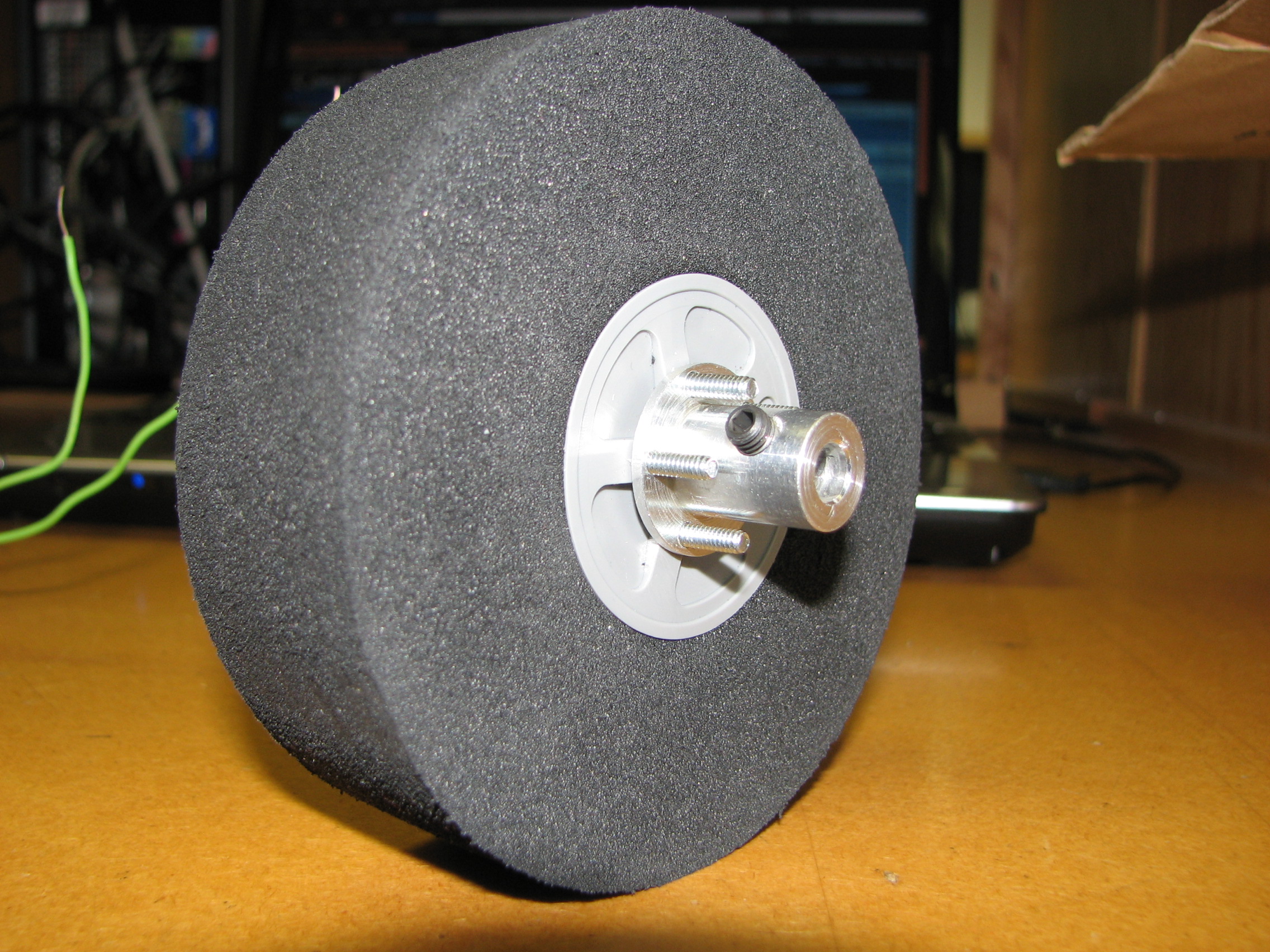
↑ The foam wheel came with plastic hubs. We purchased an aluminum hub that would allow easy connection
to the motor.
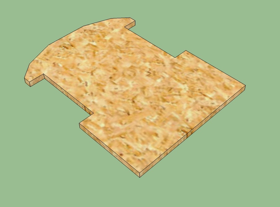
↑ The chassis designed in Google SketchUp.
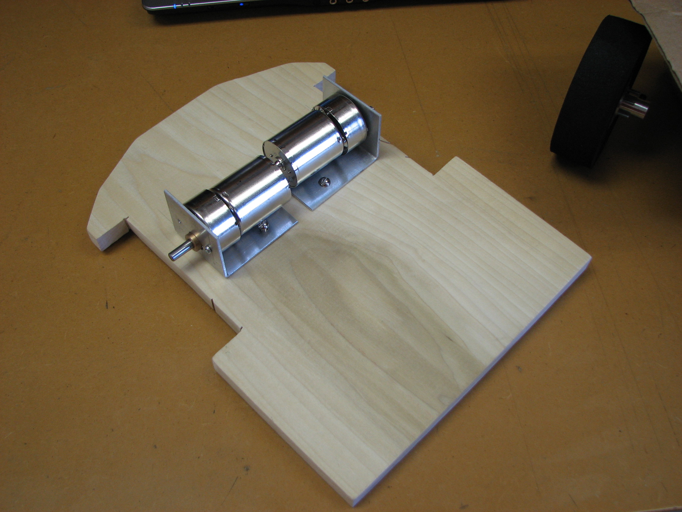
↑ The chassis is cut from wood. The motor mounts can be seen in place in this photo.
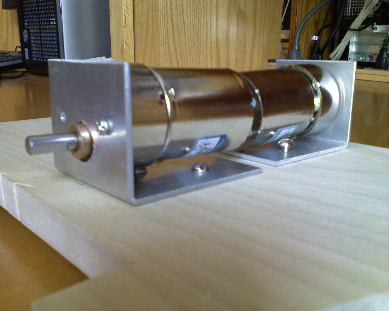
↑ Close up image of the motors attached to the fabricated motor mounts.

↑ The wheel mounted to the motor using the aluminum hub.
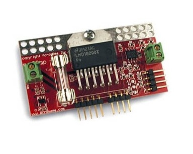
↑ H-Bridge module used to control the motors with the microcontroller.
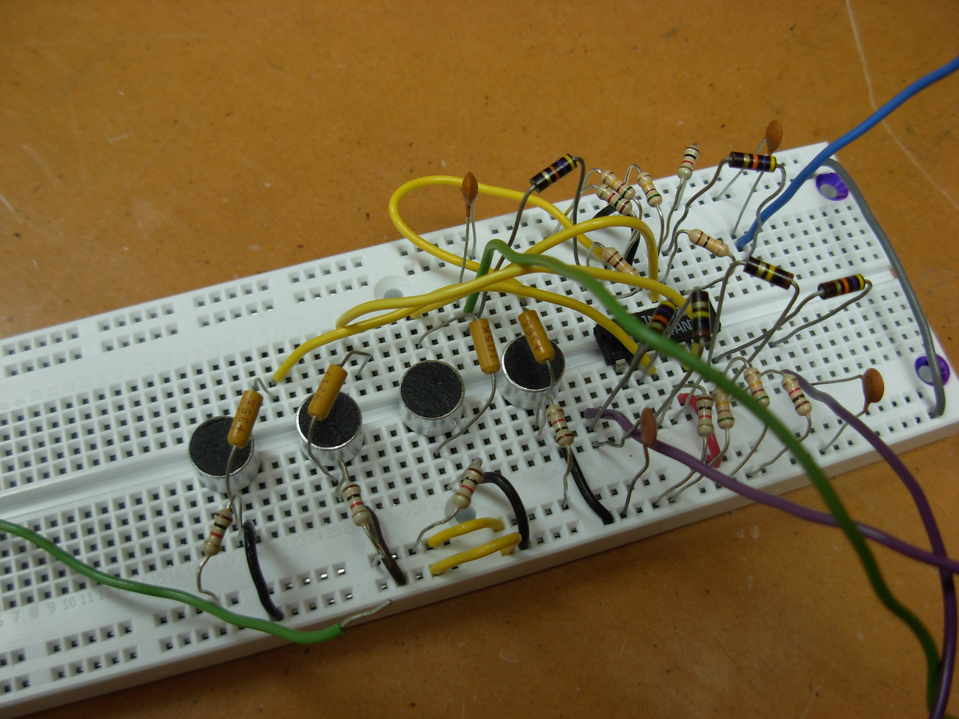
↑ The test circuitry for the microphones.
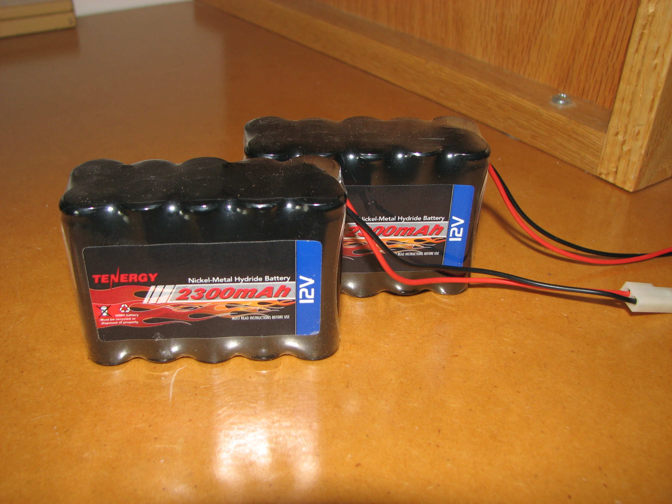
↑ The 12V batteries used to power the robot.
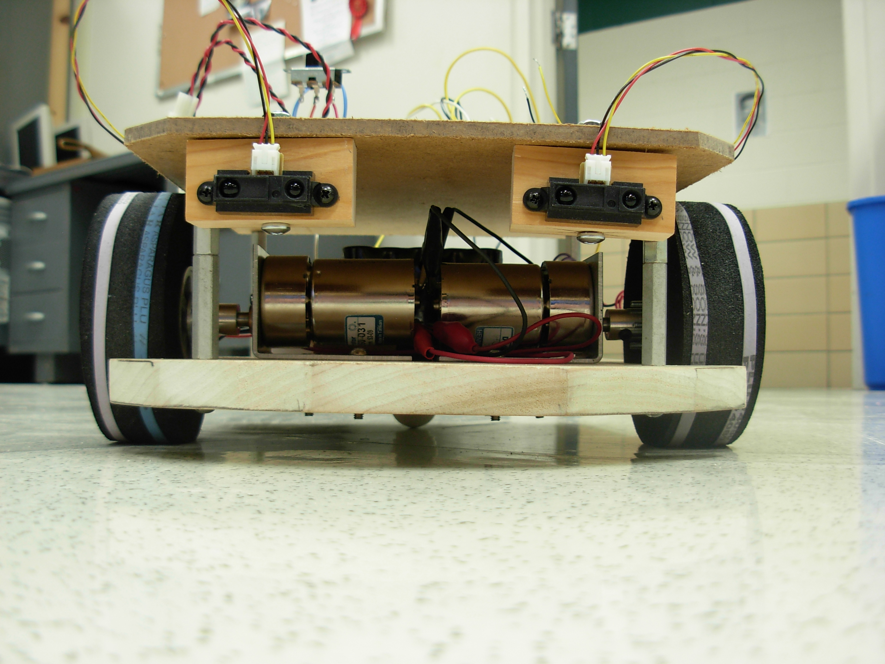
↑ From the front, you can see the dual IR sensors used for obstacle avoidance.
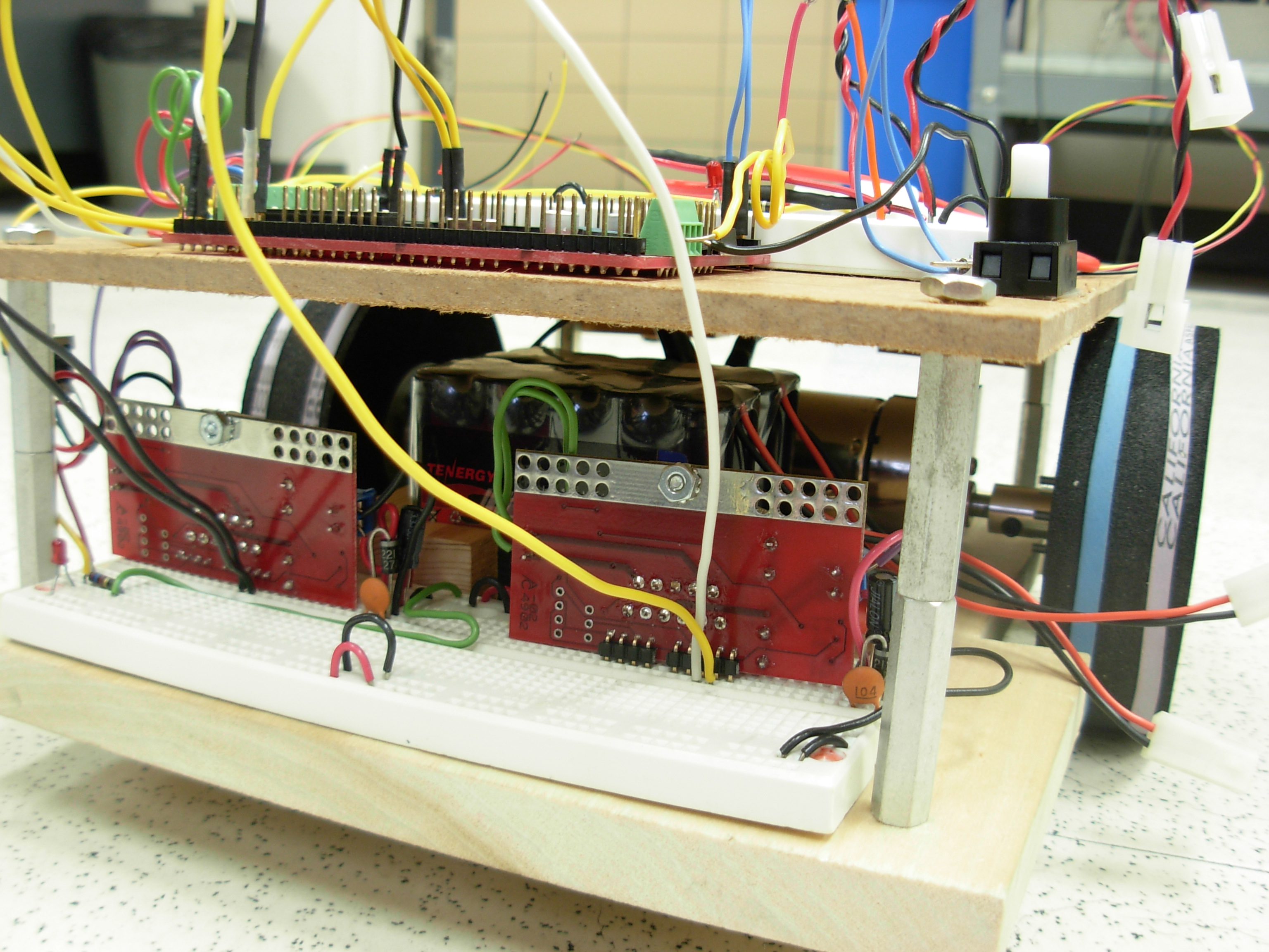
↑ From the rear, you can see the two h-bridges used to control the motors direction and speed.
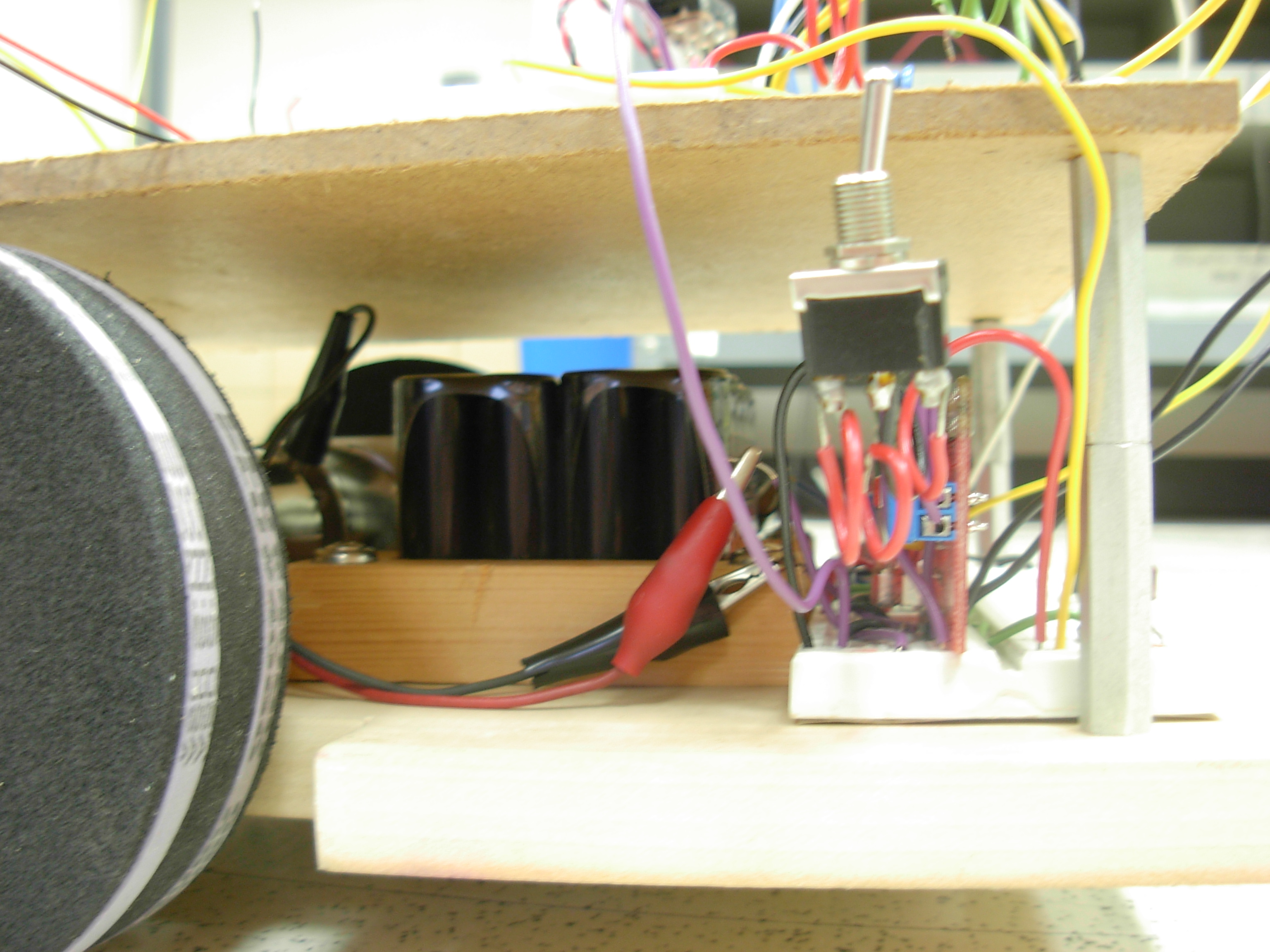
↑ From this view, you can see the batteries mounted in the middle behind the motors to keep the weight centered to improve overall traction.
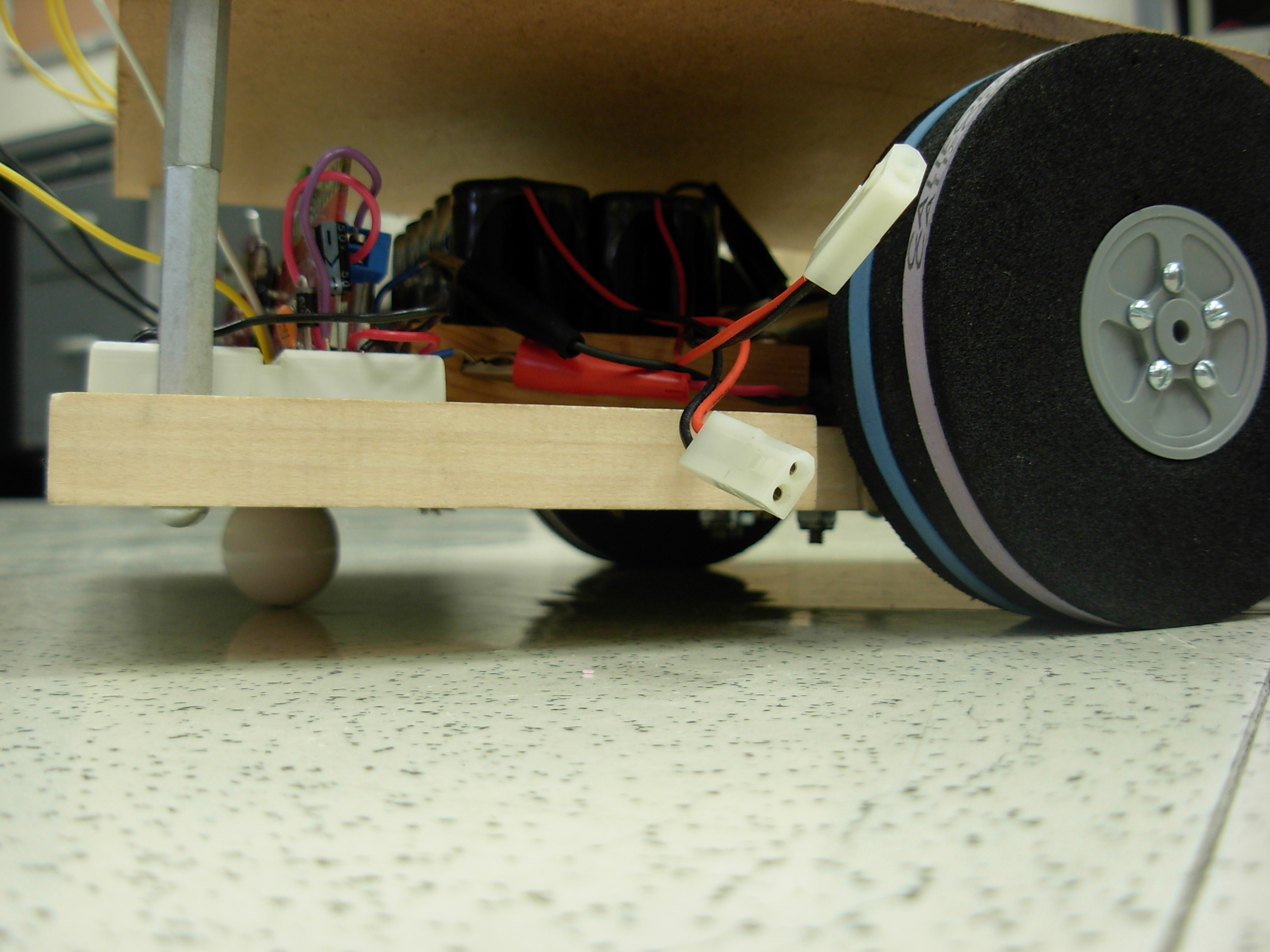
↑ This view allows you to see the three points of contact the robot has with the ground, two foam wheels with rubber bands for extra grip, and a ceramic drawer pull as a rear caster.
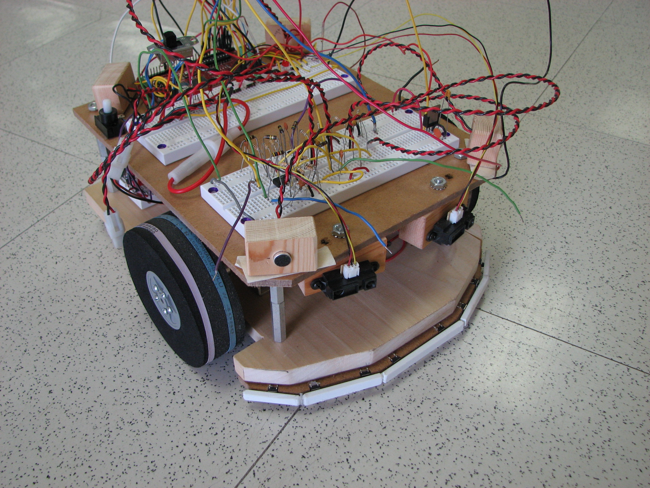
↑ The final state the chassis got to is seen above. There are four microphones, one on each corner of the upper level mounted inside a small wooden block.
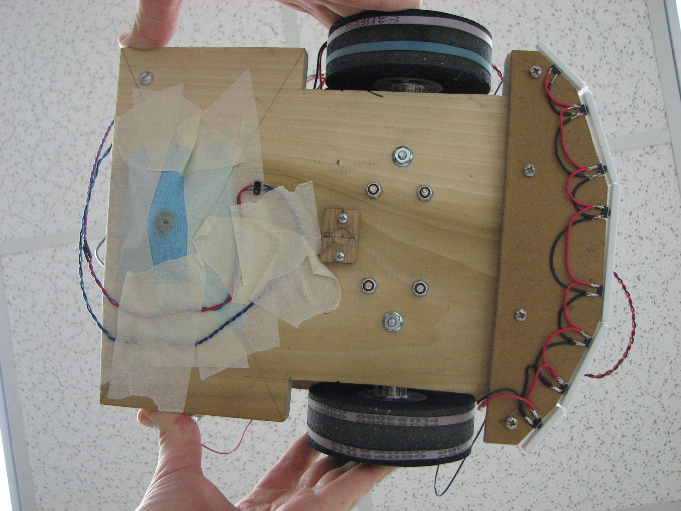
↑ On the bottom of the chassis, you can see the reflective light sensor and the wiring for the bump sensor array. The ceramic ball has been covered with cloth to stop if from squeeking on the ground.
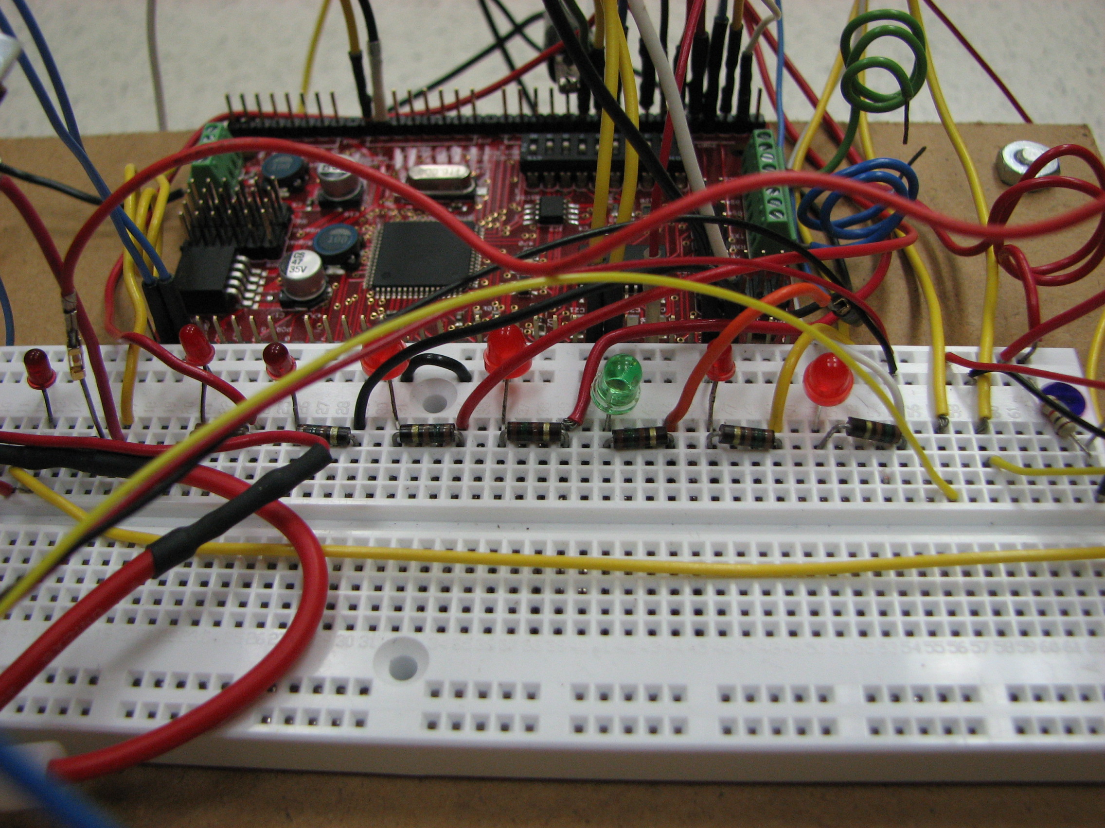
↑ This array of LEDs were used for debugging purposes.
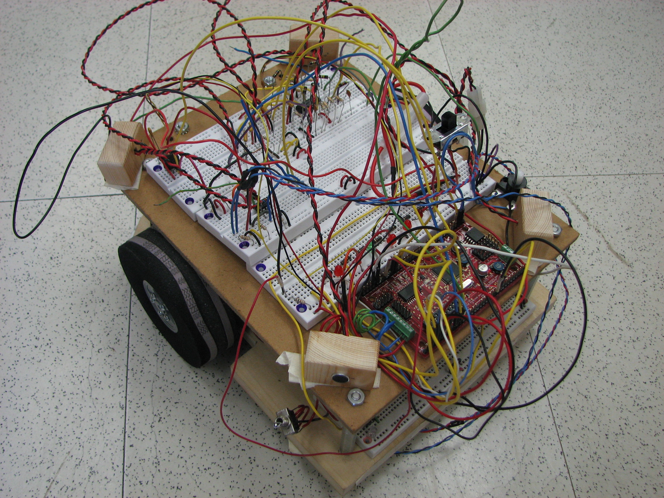
↑ The resulting mess of wires from quick testing and debugging.
Video Gallery
↑ This is testing the Analog to Digital Converter on the ATmega128 microcontroller.
The input was a 0 to 5 volt sine wave with a period of 10 seconds.
The ADC value and calculated voltage were outputted on UART0 and displayed on the PC.
↑ This is a simple program that uses an ADC to read the input of two IR sensors and will light an
LED when the voltage from the corresponding IR sensor is above 1.5 volts.
↑ Test program that controls two PWMs running off of Timer 3 at 62.5kHz.
The output of the two IR sensors control the duty cycle of the PWMs.
↑ This is testing the four microphones attached to external interrupts on the ATmega128. The microcontroller is fast enough to determine which of the four microphones detect the sound first and this is proved by moving a microphone in front of the others and viewing the corresponding LED turn on when a sound is detected.
↑ This is the final state we achieved on this project. The robot avoids objects, avoids loud sounds, and reacts to the shade of the floor tiles.