Internal Model Control
for
DC Motor
Using DSP Platform
Senior Project Proposal
Advisor: Dr. Dempsey
By: Marcus
Fair
December 13, 2007
I Summary
II Problem description
III Goals
IV Technical Specs
A. Parts list
B.
Functional requirements and Specs
V Subsystem breakdown
A.
eZdsp F2812 board
B. Pittman motor
C. H-bridge
VI Preliminary work from demos
A.
PWM demo
B.
Motor velocity control demo
VII Spring Schedule
VIII Bibliography
Summary
The goal of this project is to design, build,
and test an IMC (Internal Model Control) controller that implements neural
networks to control a Pittman GM9236C534-R2 DC motor. The project will consist
of a 32-bit TMS320F2812 digital signal
processor (DSP) that will be able to read the Simulink code using the Code
Composer Studio software. The
design for the IMC controller will be built in the Simulink software. The input
to the system will be a graphical user interface (GUI) built in the Matlab
environment, where the user will be able to enter the parameters to control the
DC motor.
Problem Description
The project involves
controlling a Pittman DC motor using a 32-bit TMS320F2812 digital signal
processor (DSP) located on the ezdsp F2812 board. This is based on the senior
mini-project where an 8051 micro-controller was used to control a Pittman DC
motor using assembly language programming. However, the DSP board will play the
role of the E-Mac kit. This project will be coded in Matlab and Simulink, which
will be automatically converted to an assembly language in order to communicate
with the DSP board. Since there will be no assembly language coding in this
project more focus and energy can be put into the control theory aspects of the
design. The overall block diagram is still based on the senior mini-project so
the plant is still the Pittman DC motor. The rotary encoder in the block
diagram will still have the same gain value from the mini-project design. The
RPM calculations that convert pulses to RPM will also have the same value since
this was based off of the same DC motor values such as gear ratio. Even though
the board will communicate with both the Matlab and Simulink environment, the
code can also be written in C-code. The 32-bit DSP processor will allow many
more algorithms such as Internal Model Control and neural network control to be
investigated. The final controller will be Internal Model Control (IMC) (an
advanced controller that can be used to minimize the effects of external
disturbances). First the feed-forward controller will be implemented to test
the experimental values of the feed-forward loop. Then the IMC (internal Model
control) design will be implemented and the results will be compared to
feed-forward controller results.
Goals
1) Learn the inputs, outputs and all of the
features of the TMS320F2812
DSP and become more familiar with the hardware.
2) Design DSP/motor hardware interface.
3) Design software for PWM generation, velocity
calculation from rotary encoder, motor direction sensing, and bi-directional
motor control signals.
4) Design closed-loop controllers for velocity
control: Single-loop proportional, proportional plus derivative plus integral
(PID), and feed-forward control test system with and without external load.
5) Design and implement IMC architecture using
neural networks on the physical system.
6) Compare conventional controller results with the IMC method.
7) Design Simulink/MATLAB
graphical user interface (GUI) for controller parameter modification.
8)
Determine the limitations of the Simulink/TMS320F2812 DSP
interface in terms of real-time execution and program memory.
Equipment List
ezdsp F2812 board
Pittman
GM9236C534-R2 DC
LMD18200 H-Bridge
SN74LVC4245A 3.3-V to 5-V shifter
Tektronix
Oscilloscope
Agilent
DC power supply
Functional
Requirements and Performance
Specifications
·
Motor speed will reach up to 834 RPM
·
Motor acceleration will increase by 98 RPM per millisecond
·
System will use a 30 VDC power supply
·
The PWM timing will be a fixed period 1 khz waveform with variable
duty cycle in increments < 0.2%
·
Motor velocity display accuracy will be within + or - 10 RPM
(battery voltage 0 to 30v)
·
Optimum gains for proportional and integral controllers will be
determined based on supply variation and external load
·
Product temperature will be from 0 to 40 degrees C
·
Rise time will be 20 ms or less
·
Overshoot will be equal to or less than 5%
·
Steady state error will be less than or equal to 5 RPM
Subsystem
Breakdown
eZdsp F2812 Board
Figure 1 shows a high-level
diagram of the eZdsp F2812
board. The input will be through a graphical user interface in Simulink that
will convert the Matlab/Simulink code using Code Composer Studio 3.0. This
software sends the code to the DSP board through the parallel port. Code
Composer is necessary to convert the code into a form that can be read by the
DSP processor. The DSP chip is then run off of the code to produce a PWM signal
that runs the Pittman Motor.
Figure 1 “Block Diagram of
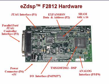
eZdsp F2812 connections”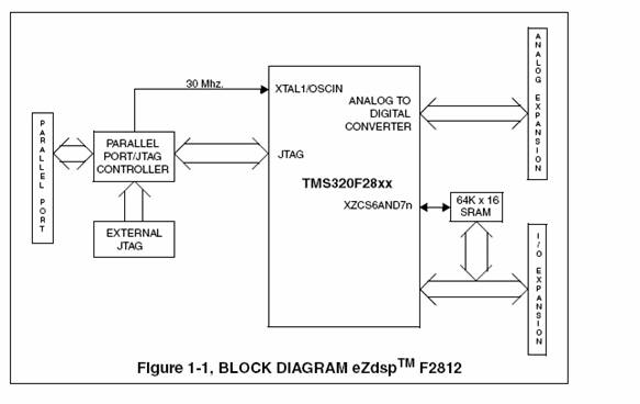 eZdsp F2812 Specs Figure 2
“ezdsp F2812 board layout”
eZdsp F2812 Specs Figure 2
“ezdsp F2812 board layout”
|
Generation |
TMS320F281x
Controllers |
|
CPU |
1 C28x |
|
Peak MMACS |
150 |
|
Frequency(MHz) |
150 |
|
RAM |
36 KB |
|
OTP ROM |
2 KB |
|
Flash |
256 KB |
|
EMIF |
1
16-Bit |
|
PWM |
16-Ch |
|
CAP/QEP |
6/2 |
|
ADC |
1 16-Ch
12-Bit |
|
ADC Conversion Time |
80 ns |
|
McBSP |
1 |
|
UART |
2 SCI |
|
SPI |
1 |
|
CAN |
1 |
|
Timers |
3 32-Bit GP,1
WD |
|
GPIO |
56 |
|
Core Supply (Volts) |
1.9 V |
|
IO Supply (Volts) |
3.3 V |
|
Operating
Temperature Range (°C) |
-40 to 85,-40 to
125 |
H-bridge and External Hardware
Figure 3 shows the single-loop controller diagram that was used for the senior mini-project. The H-bridge will be the amplifier used to step up the voltage of the PWM signal. Other external hardware such as protection circuitry will be included in the system but is yet to be determined yet.
Figure 3 “Single-loop Control
of DC motor using DSP board”
LMD18200 H-Bridge Specs
|
Delivers up to 3A continuous
output |
|
Operates at supply voltages up to
55V |
|
Low RDS(ON)
typically 0.3W per switch |
|
TTL and CMOS compatible inputs |
|
No “shoot-through” current |
|
Thermal warning flag output at 145°C |
|
Thermal shutdown (outputs off) at 170°C |
|
Internal clamp diodes |
|
Shorted load protection |
|
Internal charge pump with external bootstrap
capability |
|
Internal clamp diodes |
|
Shorter load protection |
|
Internal charge pump with external
bootstrap capability |
Pittman DC motor
The Pittman DC motor block
diagram in Figure 4 consists of a transfer function that corresponds to the
electrical side and another transfer function that corresponds to the
mechanical side. The transfers function for the electrical side and mechanical side
were calculated in the Electronic Product Design lab. The incoming signal to
the first transfer function represents a difference of the control voltage and
the feedback voltage while the output to this transfer function represents the
armature current. The current is multiplied by the torque constant gain (kt)
whose output is converted to torque. The torque is then multiplied by the
transfer function that represents the mechanical side of the motor such as
stiffness, friction, and inertia. The final output is rotational velocity. The
voltage constant gain (kv) in the feedback loop converts the rotational
velocity back into a voltage.
Figure 4 “Block Diagram of
Pittman Motor”

Motor
specs
|
Part # |
GM9236C534-R2 |
|
Gear ratio |
5:9:1 |
|
No-load
at 30V |
800 RPM, current 100
ma |
Encoder Specs
|
Input Voltage |
5V |
|
Resolution |
512 ppr (before gear reduction |
|
|
|
IMC Controller
Figure
5 shows the IMC controller used in a single feedback loop configuration. The
IMC loop consists of the plant Gp and the transfer function Nc. Nc computes the
difference between the outputs of the process and of the IMC. This difference
represents the effect of disturbances and of a mismatch of the model. The IMC
architectures have been shown to have good robustness properties against
disturbances.
Figure 5 “Block Diagram of IMC for Disturbance Rejection” 
Preliminary
Lab Work
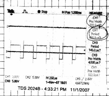
The
PWM demo utilizes the PWM 1 and PWM2 pins from the DSP board. In this demo, the
oscilloscope was connected to the PWM1 pin. In this demo, the period of the
signals were changing between 16000 and 32000 clock cycles every 1.6s. The duty
cycle of the pulse waveform is determined by the ratio of the pulse width and
the pulse period. The duty cycle of the PWM signal was changing between 50% and
75% as seen in figures 5 and 6.
Figure
6 “PWM signal at 50% duty cycle”
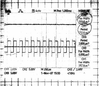
Figure
7 “PWM signal at 75% duty cycle
A
second demo was also ran in Matlab where the DC motor and H-bridge were
connected to the DSP board. Protection circuitry were connected between the DSP
board and the H-bridge since the DSP board could only work with 3.3v inputs and
outputs. The rotary encoder of the dc motor was ran off of the 5v internal
power supply of the DSP board. The motor speed and other parameters were set in
the MATLAB GUI. The speed setting was sent to the controller code running on
the DSP via RTDX. The controller constantly adjusted the duty cycle of the PWM
waveform driving the motor to maintain the desired speed. This demo was a way
to experiment with how the hardware components of the project would connect
with the DSP board and also to experiment with the MATLAB GUI.
|
|
|
|
Spring Semester Schedule |
|||||
|
|
|
|
|
|
|
|
|
|
|
week |
|
|
|
|
|
|
|
|
|
1-4 |
|
|
Build and test single-loop
controller, Design initial Gui layout |
|
|
|
||
|
5 |
|
|
Build and test feed-forward
controller |
|
|
|
|
|
|
6-8 |
|
|
Train the neural network in
simulation and experimental |
|
|
|
||
|
9 |
|
|
Implement neural network as
feed-forward control |
|
||||
|
10 |
|
|
Implement IMC with linear model |
|
|
|
||
|
11 |
|
|
Implement IMC with neural network |
|
|
|
||
|
12 |
|
|
Design alternative neural network
method, final testing, final Gui design |
|
|
|
||
|
13-14 |
|
|
Final documenation |
|
|
|
|
|
The
first reference is a link to the website that contains the technical reference
for the DSP board. It contains the pinout diagram, input and outputs, memory
layout, and hardware and software features for the ezdsp board. The 2nd link is
a reference to the theory of IMC controllers. The 3rd link is a reference
to the datasheets for the Pittman motor and the h-bridge.
Bibliography
http://c2000.spectrumdigital.com/ezf2812/
http://lorien.ncl.ac.uk/ming/robust/imc.pdf
http://blackboard.bradley.edu/webapps/portal/frameset.jsp?tab_id=_2_1&url=%2Fwebapps%2Fblackboard%2Fexecute%2Flauncher%3Ftype%3DCourse%26id%3D_41146_1%26url%3D