Internal Model Control
for
DC
Motor
Using DSP Platform
Advisor: Dr. Dempsey
By: Marcus Fair
November 12, 2007
Problem Description
The project
involves controlling a Pittman DC motor using a 32-bit TMS320F2812 digital
signal processor (DSP) located on the ezdsp F2812 board. This is based on the
senior mini-project where an 8015 microcontroller was used to control a Pittman
DC motor using assembly language programming. However, the DSP board will play
the role of the E-Mac kit. This project will be coded in Matlab and Simulink,
which will be automatically converted to an assembly language in order to
communicate with the DSP board. Since there will be no assembly language coding
in this project more focus and energy can be put into the Control theory
aspects of the design. The overall block diagram is still based on the senior
mini-project so the plant is still the Pittman DC motor. The rotary encoder in
the block diagram will still have the same gain value from the mini-project
design. The RPM calculations that convert pulses to RPM will also have the same
value since this was based off of the same DC motor values such as gear ratio.
Even though the board will communicate with both the Matlab and Simulink
environment, the code can also be written in C-code. The 32-bit DSP processor
will allow many more algorithms such as Internal Control Model and neural
network control to be investigated. The final controller will be Internal Model
Control model (IMC) which is an advanced controller that can be used to
minimize the effects of external disturbances. The feed-forward design will
first be put together to test the experimental values of the feed-forward loop
first. Then the IMC (internal Model control) design will then be implemented
and then the results will be compared to feed-forward controller results.
Goals
1) Learn the
inputs, outputs and all of the features of the TMS320F2812 DSP
and become more familiar with the hardware.
2) Design DSP/motor hardware interface.
3) Design
software for PWM generation, velocity calculation from rotary encoder, motor
direction sensing, and bidirectional motor control signals.
4) Design
closed-loop controllers for velocity control: Single-loop proportional,
proportional plus derivative plus integral (PID), and feed-forward control test
system with and without external load.
5) Design and
implement IMC architecture using neural networks on the physical system.
6) Compare conventional controller results with the IMC method.
7)
Design Simulink/MATLAB graphical
user interface (GUI) for controller parameter modification.
8) Determine the limitations of the
Simulink/TMS320F2812 DSP interface in terms of real-time execution and program
memory.
Subsystem
Breakdown
Figure 1 shows a high-level
diagram of the F2812 board. The input will be through a graphical user
interface in Simulink that will convert the Matlab/Simulink code using Code
Composer Studio 3.0. This software sends the code to the DSP board through the
parallel port. The Code composer is necessary to convert the code into a form
that can be read by the DSP processor. The DSP chip is then run off of the code
to produce a PWM signal that runs the Pittman Motor.
Fig. 1
“Block Diagram of eZdsp F2812 connections”
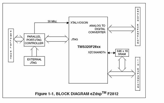
Figure 2 shows the single-loop controller diagram that was used for the senior mini-project.
Fig. 2 “Single-loop
Control of DC motor using DSP board”
The Pittman DC motor block
diagram in Figure 3 consists of a transfer function that corresponds to the
electrical side and another transfer function that corresponds to the
mechanical side. The incoming signal to the first transfer function represents
a difference of the control voltage and the feedback voltage while the output
to this transfer function represents the armature current. The current is
multiplied by the torque constant gain (kt) whose output is converted to
torque. The torque is then multiplied by the transfer function that represents
the mechanical side of the motor such as stiffness, friction, and inertia. The
final output is rotational velocity. The voltage constant gain (kv) in the
feedback loop converts the rotational velocity back into a voltage.
Fig. 3 “Block Diagram of
Pittman Motor”
Fig. 4 shows the internal model control used in a single
feedback loop configuration. The IMC loop which consists of the plant Gp and
the transfer function Nc computes the difference between the outputs of the
process and of the IMC. This difference represents the effect of disturbances
and of a mismatch of the model. The IM architectures have been shown to have
good robustness properties against disturbances.
Fig. 4 “Block Diagram of
IMC for Disturbance Rejection” 
References
eZdspTM F2812 2003 DSP
Development Systems
http://www.spectrumdigital.com/product_info.php?&products_id=138
Reference