Single Side Band (Hilbert Transform) Amplitude Modulation
Fig 1 System Level Block Diagram of SSB AM.
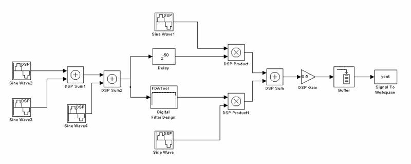
Fig 2 Simulink SSB Block Diagram.
Generated Sine wave = 1Sin(1000*2*pi*t) This is the Carrier Frequency.
x(t) = 1Sin(100*2*pi*t) + 1Sin(300*2*pi*t) + 1Sin(500*2*pi*t) These are the
signals entered into the system.
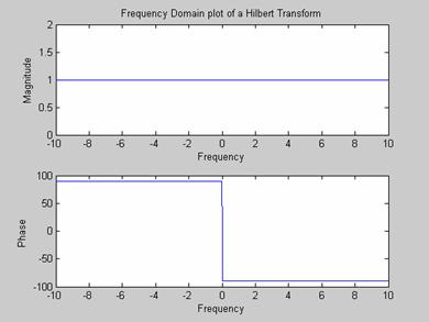
Fig 3 The Hilbert Transform
The Hilbert transform is a type of filter that has a constant gain of 1 and a
constant phase shift of 90 degrees
over the whole frequency band. As shown if Fig 2, the Hilbert transform is
constructed with a Nth order FIR filter
and a delay of N/2. In this case a 100th order FIR filter was designed.
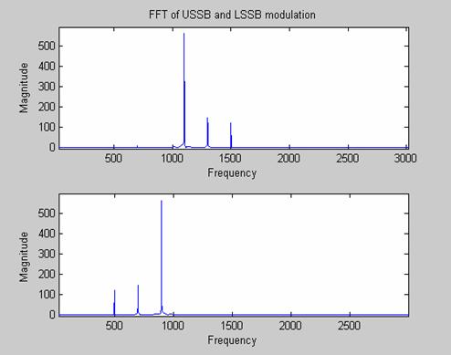
Fig 4 MATLAB simulations of the SSB modulation.
Note: Both Upper SSB and Lower SSB are shown. This can be switched by
choosing which signals
(cosine or sine) to multiply to the entered signal. See Fig 1.
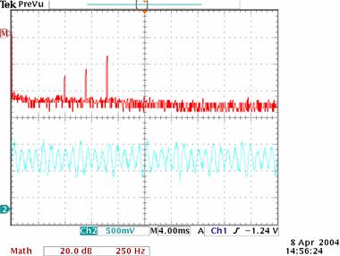
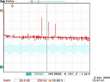
Fig 5 Experimental simulations of USSB and LSSB.
Compare to Fig 4.