2 Point Quadrature Amplitude Modulation
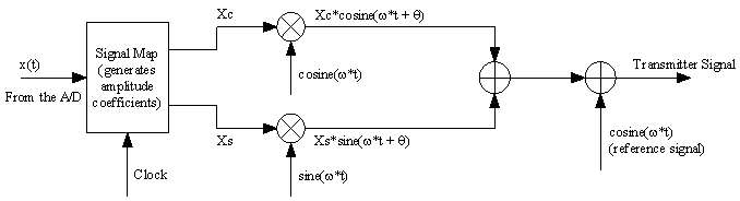
Fig 1 System Level Block Diagram of 2 Point QAM
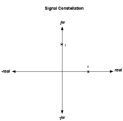
Fig 2 Signal Constellation of 2 Point QAM
Each bit is mapped to either the in-phase or quadrature-phase component, as
shown on the map.
This is a purely digital scheme.
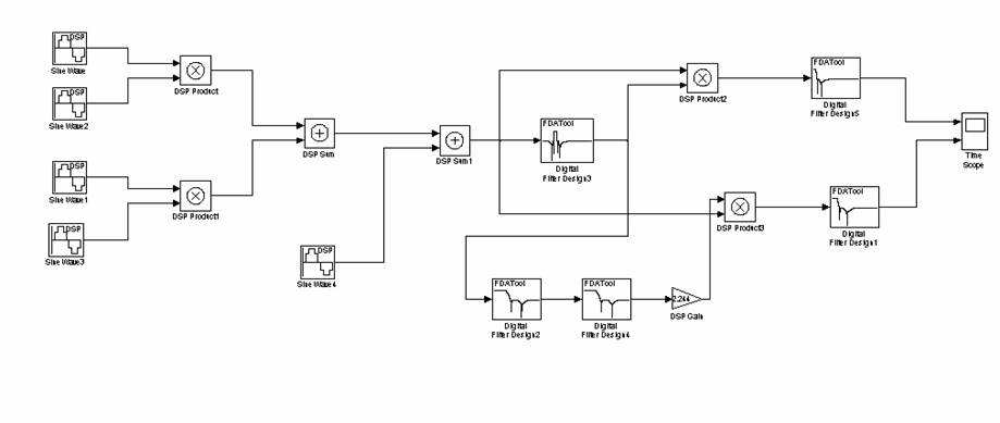
Fig 3 Simulink Block Diagram of 2 Point QAM.
Generated Sine wave = 1sin(1000*2*pi*t) This is the Carrier Frequency.
x(t) = 1Sin(200*2*pi*t) + 1Sin(400*2*pi*t) These are the
signals entered into the system.
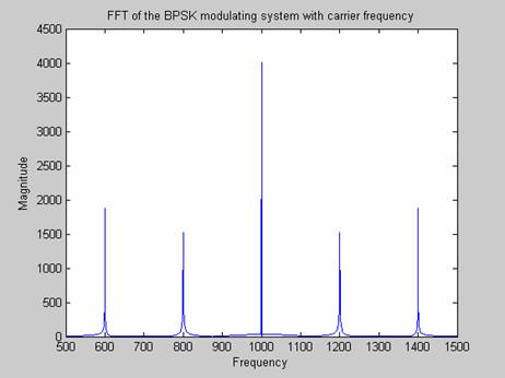
Fig 4 MATLAB FFT of 2 Point QAM.
Note the carrier at 1000 Hz and the two signals at 1000Hz +/- 200Hz, 1000Hz +/-
400Hz.
Due to the complexity of the Simulink blocks used, this system could not be
loaded on the TI board, and
could only be verified within MATLAB.