Fig. 1 Check distance flowchart
This week I have worked on finalizing the code for Lost Edge/Turn Mode. The first flowchart is called from Straight mode. It checks to see if the position of the car is at an intersection. If it is not at an intersection, the module will call the lost edge module (See Fig. 4). If it is at an intersection, the module will call the check status function. (See Fig. 3). The flowchart in Fig. 2 is used by the check distance module to determine if the distance is within an allowable tolerance level. The check status function will determine if the vehicle should go forward at this intersection or turn left. The go forward function is in Fig. 5. Fig. 6 represents how the vehicle will maneuver in a left turn. From point 1 to point 2, the vehicle will have its wheels full left and will repeated poll the compass. Once the vehicle heading is equal to the desired heading, it has reached point 2. Next the vehicle will continue to go full left unitl both sensors read concrete. Once both sensors are on concrete, the wheels will be steered so they are going straight. The vehicle will continue in the direction and poll the sensors. Once the right sensor is detecting grass, we have two choices. It might be possible to call straight mode from there and exit the routine. If determined during testing that this is not acceptable. From point 3 to 4 the wheels will be steered right and the compass will be polled until the vehicle heading is equal to the desired heading. At which point straight mode can be called and the the routine exited. Discussion of this weeks work continues below the figures.

Fig. 1 Check distance flowchart

Fig. 2 Check tolerance flowchart

Fig. 3 Check status flowchart

Fig. 4 Lost Edge flowchart

Fig. 5 Go forward flowchart

Fig. 6 Turn left diagram
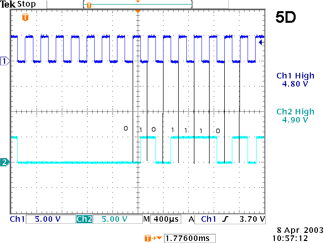
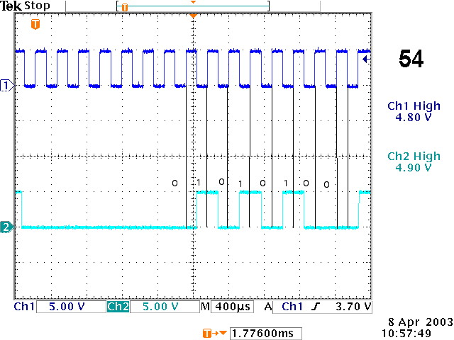
I completed the hardware integration with the EMAC. I had problems with a port 4 signal not being low enough to switch the relay. I ended up putting a pull down resistor from the base of the transistor. I also tested the poll compass software. Below are some scope readings from the digital compass that were read by the EMAC. The hex values in the upper right hand corner are the values read by the EMAC. Looking at the figures you can see that these readings agreed with what came from the compass.


Fig. 7 Compass Readings
Next, I ran into problems with the A/D converter. I've determined that the noise on the line while the h-bridge is on is affecting the readings to control steering. To correct this problem I have added some code in the read A/D function to average 5 readings. This in a sense acts as a low pass filter in software. I have not had a chance to test this new function yet.
On lab day Erin and I took the vehicle for our first field test. The test did not go as expected. When the vehicle was turned on with the motor hardware connected to the EMAC, it would no longer run the straight mode module on the EMAC. So, the vehicle only turned left. Once we went back inside, I was looking at our test code and found some problems. Our test code was a compilation of Erin's efforts and mine. The two of our modules were conflicting in several aspects. So, I have merged the two modules into one project now. We will be running tests on this module next week. Below are links to the first draft of our combined code.
Main Module
LCD and Keypad Module
Motor, Linear Actuator and Compass Module
Lost Edge and Turn Module
Miscillaneous Function Module
Earlier this week I combined Ramona's code for turning the wheels of the week and running the motor with my code for the acoustic sensors and straight mode. In lab, I tested this code, and everything seemed to be working together. We took the vehicle outside to test straight mode, and we used a laptop that we got from Nick to help with debugging. I added a feature that would allow the user to press a key to start the motor and press a key to stop the motor. A=start and F=stop. The first thing I looked at was to see if the sensors were responding to the sidewalk and grass as I had expected to them to, and to my relief, they were. There was a distinct difference between the response of grass and the response of the sidewalk. Also, the software was working correctly as far as turning the wheels right or left in response to the sensor outputs. See Figure 8, 9, and 10 below. When the sensors are in the configurations seen in Figures 8 and 9, then the vehicle is in straight mode. When the sensors are in the configuration seen in Figure 10, the vehicle is in turn mode.

Figure 8. Sensor Configuration where Sensor 1 = sidewalk and Sensor 2 = grass
When the vehicle is in the configuration such that sensor 1 = sidewalk and sensor 2 = grass as seen in Figure 8, then the vehicle should turn slightly left. While testing outside, the vehicle responded correctly to this configuration by turning the wheels slightly left.

Figure 9. Sensor Configuration where Sensor 1 = grass and Sensor 2 = grass
When the vehicle is in the configuration such that sensor 1 = grass and sensor 2 = grass as seen in Figure 9, then the vehicle should turn slightly right. While testing outside, the vehicle responded correctly to this configuration by turning the wheels slightly right. Basically, the vehicle will zig-zag along the edge of the sidewalk while in straight mode, and this will insure that the vehicle does stay on the edge of the sidewalk.

Figure 10. Sensor Configuration where Sensor 1 = sidewalk and Sensor 2 = sidewalk
When the vehicle is in the configuration such that sensor 1 = sidewalk and sensor 2 = sidewalk as seen in Figure 10, then the vehicle should enter turn mode. Currently, we are just testing straight mode, so the LCD will just display the word "TURN" to indicate that the vehicle is in turn mode, and the LCD would display "TURN" during this configuration while testing outside. Experimental testing outside showed that the sensor code was working correctly and as expected. This is a huge relief because I thought that I might encounter problems with the sensors not reacting as I had planned. Note: All of this initial testing outside was done without the motor on.
When we would start the motor of the vehicle to try testing the vehicle moving forward, everything went wrong. The vehicle went too fast, and the wheels were no longer responding to the sensors. Actually, the sensors had stopped sampling all together. It appeared that when we started the motor, the program was getting stuck somewhere and never returning to the other subroutines. I believe this problem has something to do with conflicts between Ramona's code and my code. Ramona worked on the project, and she has the modules linked above. We will get outside and do some more testing and debugging next week. All in all, I think our first testing went fairly well. I am extremely happy to see the sensors respond to the sidewalk and grass surfaces as I had planned for them to.
Return to Note links