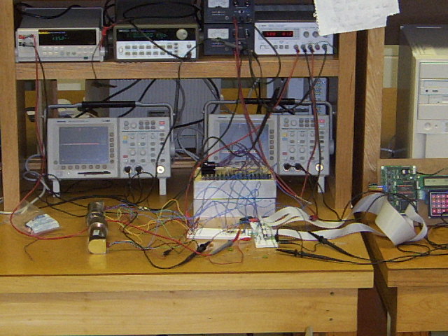
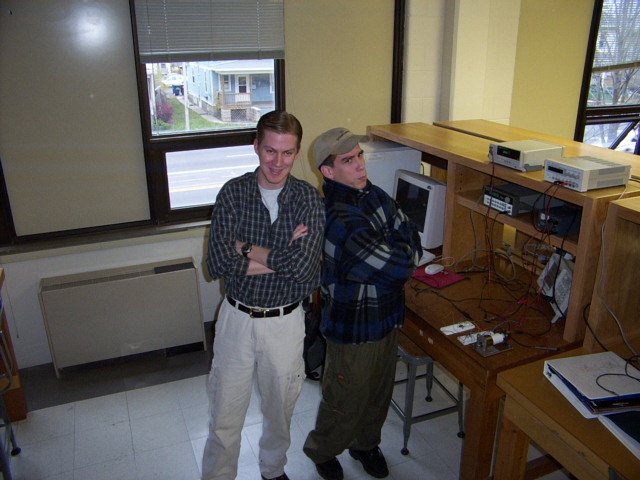
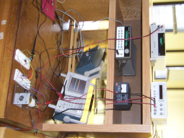
Picture_0024.jpg Our lab bench with equipment. We like to have 2 of everything. Its all about reliability.
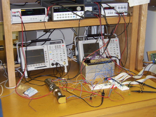
Picture_0028.jpg Another picture of the lab bench.
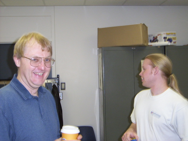
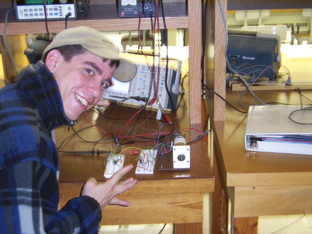
Picture_0022.jpg Dr. Dempsey and fellow class mate who both idolize Rob and Randall for being so good at everything they do.
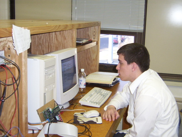
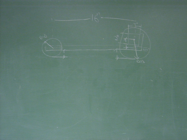
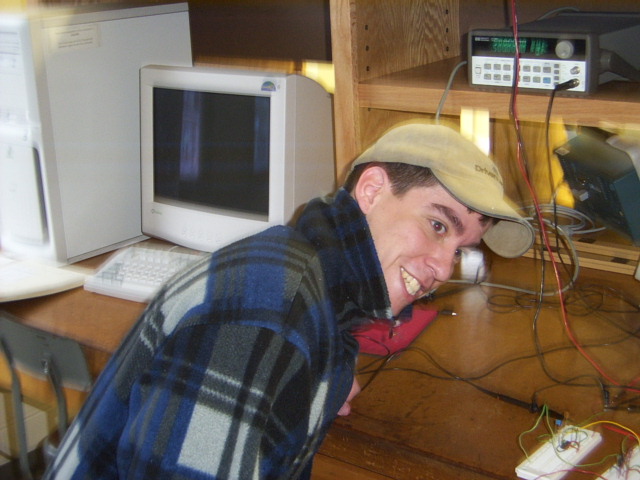
Picture_0023.jpg Rob working on his assembly code. (No that is not a Diet Pepsi near the lab equipment. Sorry Chris M.)Picture_0058.jpg The original "Traxx" chalk board sketch.
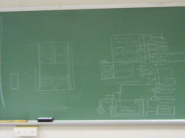
SP - Chalk Design.JPG Randall's chalk board design.
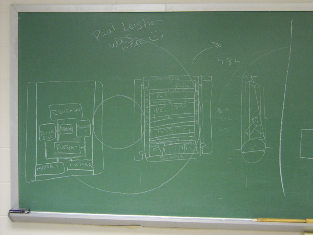
SP - Chalk Paul.JPG Paul Leisher OWNED our project by the narrow minded use of graffiti.
SP - No Clue.JPG M.C. Rob and D.J. Randall
SP - Retard.JPG Now we know how Randall feels toward his lab partner Rob. (Randall named all these pictures)SP - Tools of the Trade.JPG and this one too.
SP - West Side Circuit.JPG Rob displays his affiliation with the WEST SIDE.
SP_-_No_Clue.JPG Yeah....
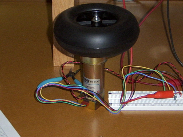
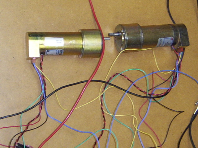
Picture_0007.jpg a Pitman motor and 6 inch wheel.
Picture_0008.jpg another motor picture without the wheel.
Picture_0055.jpg At least we have the same wheels.Picture_0025.jpg Another useless picture of the motors. Who was taking these pictures?
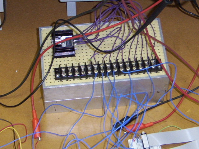
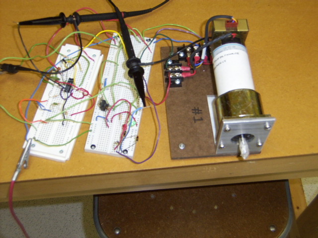
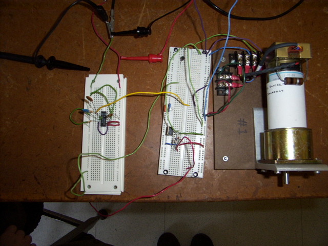
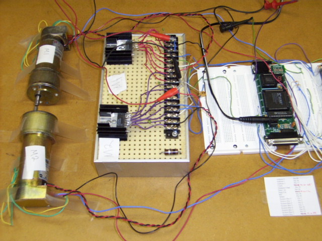
Picture_0026.jpg The H-Bridge, motor driver circuit thingy.
Picture_0059.jpg We were bored, so we attached some tape to the motor shaft, and turned it on.
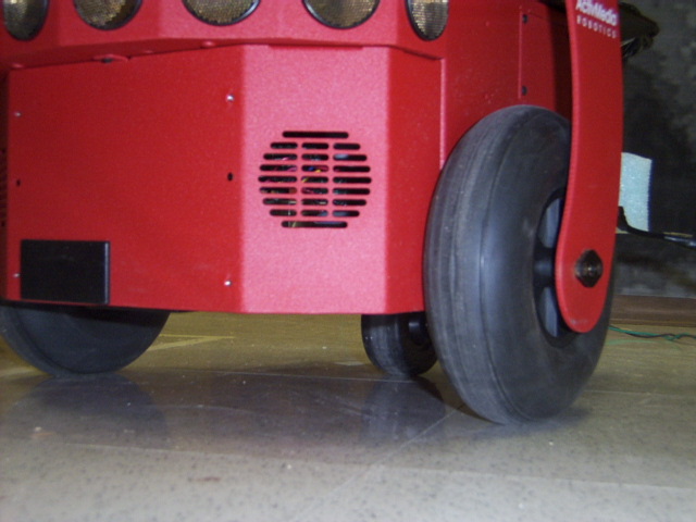
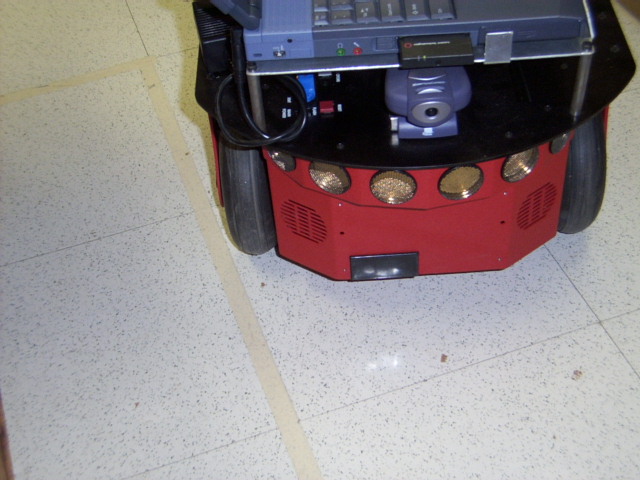
Picture_0054.jpg The $4000 version of our project. (This one actually works)
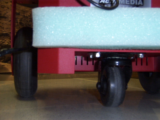
Picture_0056.jpg The caster on the $4000 robot. We need one of these for ours!
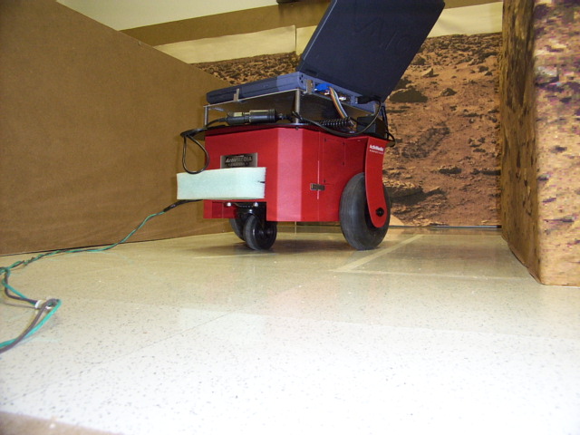
Picture_0057.jpg The mission to Mars
Picture_0006.jpg the EMAC board with 8051 micro controller.
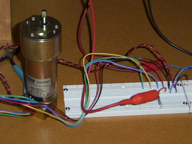
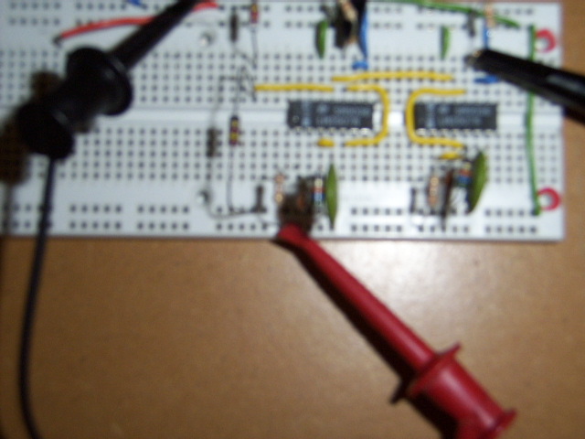
Picture_0009.jpg the two frequency to voltage converters (Randall took this picture, that is why its fuzzy).
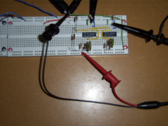
Picture_0010.jpg another shot of the F to V's on a bread board.Picture_0027.jpg A lot of wires!
SP - The Circuit.JPG I think you can figure this one out yourself.
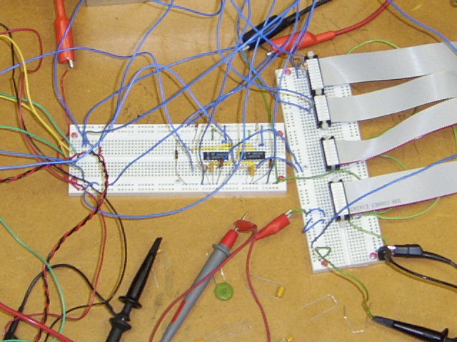
Picture_0276.jpg The Frequency to voltage converters were replaced with a CPLD. The CPLD was engineered to compute two frequencies with 8 bit accuracy. The CPLD was then interfaced to the 8051 EMAC. Eventually 2 CPLDs were required. One computes the speed and turning angle, while the other computes the distance traveled.
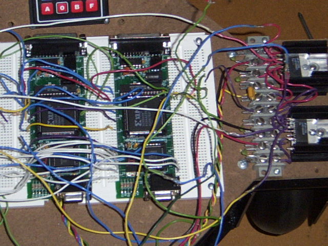
Picture_0295.jpg Here are the two CPLDs used in the project.
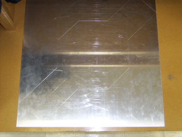
Picture_0273.jpg The platform before being cut from the aluminum sheet
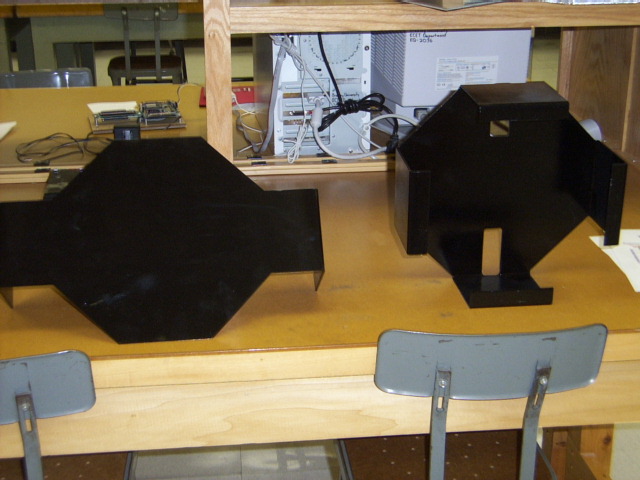
Picture_0282.jpg The platform after being cut and painted.
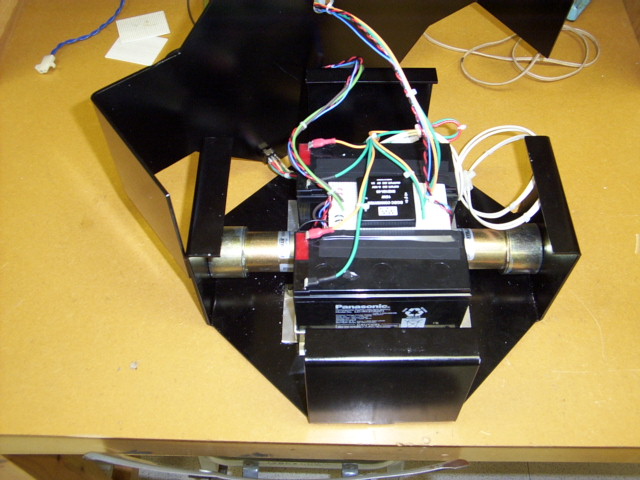
Picture_0281.jpg The platform with motors, batteries, and wiring.
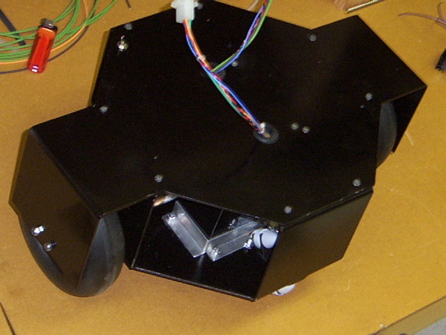
Picture_0277.jpg The Platform with motors, wheels, casters, and connectors for the electronics.
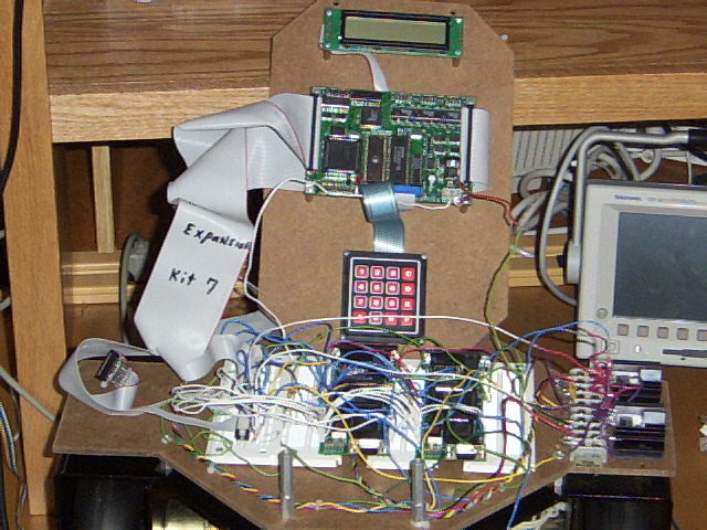
Picture_0297.jpg The complete platform with electronics, microprocessor, 2 CPLDs, keypad, and display.
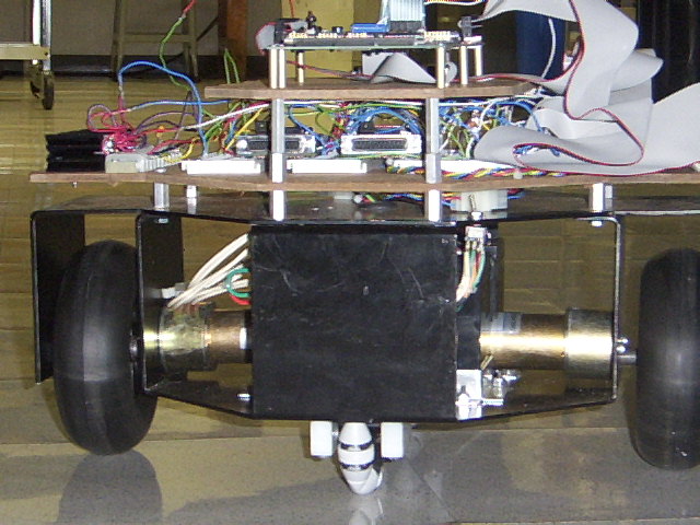
Picture_0299.jpg The vehicle and electronics viewed from the side. Notice the 3 layers.
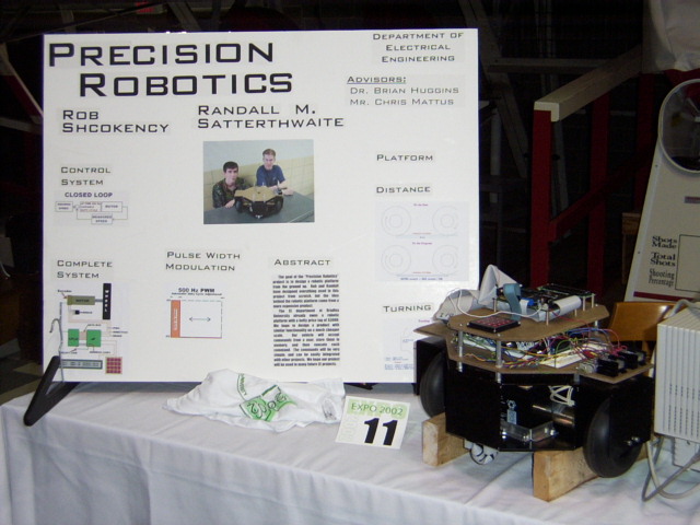
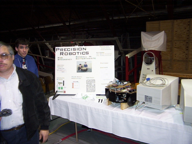
Picture_0288.jpg Our project display for the EXPO.
Picture_0289.jpg Another picture of the EXPO.