|
Functional Description |
||||||||
Autonomous Tracking and Intercepting Vehicle Utilizing Image Processing
Peter Knaub Mike Barngrover Andy Lovitt
Project AdvisorsDr. B Huggins Dr. O Malinowski
The goal of this project is to build an autonomous vehicle, which tracks and intercepts a moving target of predetermined geometry. The sole method of recognizing the target is imaging processing. After the target has been identified the vehicle will move to intercept. Once the tracker gets close enough to the target to trigger a proximity sensor, the tracker and target will shutdown. Inputs and Outputs
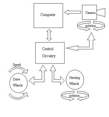
Figure 1 shows the system block diagram relating the inputs to the outputs. The photons are the main input to the system. The digital camera converts the photons to a digital image. The camera image is the only way the system can identify and track the target. The camera rotation, wheel speed, and wheel direction are all controlled through the micro-controller and are fed back for closed loop control. So the values are also read so the exact state of the system can be determined at anytime The digital compass is used to acquire a reference direction for the system. The proximity sensor is used to determine when the tracker and target are close enough together to indicate a successful intercept. The status LEDs indicates the status of the system visually. Modes of OperationTarget AcquireIn this mode the vehicle maintains its current position while sweeping the camera through its rotational range to locate the target. If after a predetermined amount of time the target is not located, the vehicle will move to another position, then continue to sweep the camera. Comparing the camera image to predefined characteristics stored on the computer will assist the computer in recognizing the target. Once the target is acquired the vehicle will enter into either bore sight intercept mode or prediction intercept mode. Bore-Sight InterceptIn this mode the system intercepts the target by keeping the vehicle direction in-line with the camera’s bore-sight while maintaining the bore-sight of the camera on the target. The computer controls the rotation of the camera. The micro-controller then uses the camera rotation input to keep the angle between the bore-sight and the vehicle direction to a minimum. Prediction InterceptIn this mode the computer performs calculations on the camera image to determine the speed and direction of the target. It then uses the target trajectory model in its memory to predict where the target will likely be a certain amount of time later. This mode uses a much more complicated algorithm on the computer. The micro-controller code is also more complicated because it must keep all the commands for relative movement and absolute movement organized.
Figure 1. General block diagram relating inputs to outputs
|
||||||||
|
October 28, 2001 |
||||||||
