|
How the blocks interact, we refer to people who did this as Block-heads |
||||
|
Autonomous Tracking and InterceptingVehicle Utilizing Image Processing
Peter Knaub Mike Barngrover Andy Lovitt
Project AdvisorsDr. B Huggins Dr. O Malinowski The goal of this project is to build an autonomous vehicle, which tracks and intercepts a moving target of predetermined geometry. The sole method of recognizing the target is imaging processing. After the target has been identified the vehicle will move to intercept. Once the tracker gets close enough to the target to trigger a proximity sensor, the tracker and target will shutdown. Figure 1 shows the system-level block diagram for the project.
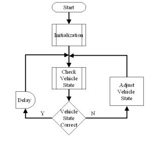
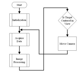
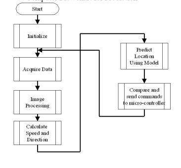
Figure 1 Subsystem Descriptions: Camera: Converts photons and makes them into a usable image for the computer Inputs: Photons Output: Digital Image to the computer via the TWAIN interface Modes: Acquire: Capture Image Bore-sight: Capture Image Prediction: Capture Image Camera Controller: Moves shaft of the motor to position the camera according to the control signal Inputs: Control signal from the micro-controller-could be analog or digital Output: Shaft rotation, position signal Modes: Acquire: Rotate camera Bore-sight: Rotate camera Prediction: Rotate camera Computer: Performs image processing and prediction on target trajectory. Refer to figure containing flow chart. Inputs: Digital image from camera Output: Digital communication to the micro-controller Modes: Acquire: Determine target and setup intercept programming Bore-sight: Determine target and center in the field of view Prediction: Determine target and predict trajectory and output status to the micro-controller. More detail of process under each mode as indicated by flow chart Micro-Controller: Used to control speed, direction, status LED’s, rotary encoder, linear actuator, and proximity sensor. Refer to software flow chart Inputs: Communication from computer, proximity signal, camera position signal, electronic compass, linear encoder, and rotary encoder Outputs: Camera control signal, speed signal, direction signal, and status signal Modes: Acquire: Control camera position Bore-sight: Align bore-sights of vehicle and camera Uses proximity, camera position, linear encoder, and rotary encoder signals to adjust speed and direction signals. Prediction: Execute trajectory commands sent by PC Uses PC com., electronic compass, rotary encoder, linear encoder, and proximity signals to adjust the speed and direction signals Status LED’s: To indicate status of the system, such as, calibration mode, acquire mode, bore-sight mode, prediction mode, or various errors. Inputs: Digital data from bus of micro-controller Output: Visual light Modes: Acquire: Diagnostic status of hardware and micro-controller Bore-sight: Diagnostic status of hardware and micro-controller Prediction: Diagnostic status of hardware and micro-controller Power Electronics for Actuator: Converts actuator control signal from micro-controller to power for actuator. Inputs: Analog signal proportional to desired direction of the wheels Output: Power analog signal to drive the actuator motor Modes: Acquire: none Bore-sight: Converts direction signal from micro-controller to power for actuator. Prediction: Converts direction signal from micro-controller to power for actuator. Actuator System: Electromechanical device to adjust direction of vehicle. Inputs: Signal from power electronics Output: direction of the wheels Modes: Acquire: none Bore-sight: Change direction of the wheels. Prediction: Change direction of the wheels. Power Electronics for Speed Control: Converts motor control signal from micro-controller to power vehicle motor. Inputs: Pulse Width Modulation signal Output: Power analog signal Modes: Acquire: none Bore-sight: Converts signal from micro-controller to power motor. Prediction: Converts signal from micro-controller to power motor. Motors: Controls angular velocity of wheels. Inputs: Power signal representing speed Output: Angular velocity of the wheels Modes: Acquire: none Bore-sight: Controls angular velocity of the wheels. Prediction: Controls angular velocity of the wheels. Rotary Encoder: Converts signal from motor to a proportional signal for angular velocity. Inputs: Signal from motor Output: Signal proportional to angular velocity of the wheels Modes: Acquire: none Bore-sight: Converts signal from motor to a proportional signal for angular velocity. Prediction: Converts signal from motor to a proportional signal for angular velocity. Proximity Sensor: Signals when vehicle has successfully intercepted target Inputs: Electromagnetic Wave Output: Digital status data Modes: Acquire: none Bore-sight: Determine if intercept is successful. Prediction: Determine if intercept is successful. Electronic Compass: Converts compass bearing to digital signal Inputs: The earth’s magnetic field Outputs: The vehicle’s compass direction Modes: Acquire: None Bore-sight: None Prediction: Used to control the trajectory of the vehicle Program Flow ChartsMicro-controller
PC for Bore-Sight (show signal from which uc control signal derived)
PC for Prediction (show signal from which uc control signal derived) |
||||
|
|
||||