Automatic Recharging System for Autonomous Robot
Final Project Proposal
By Dexter Travis
Advisors: Dr. Huggins and Dr. Malinowski
Project Summary
The primary goal of this project shall
be to upgrade the Pioneer1 robot made by Activemedia Corporation. This robot was purchased as a part
of the Telerobotics 2001 project at
Functional Description:
The purpose of this project shall be to upgrade and enhance the operation of “Telerobotics 2001” robot. This robot is a Pioneer 2-DX produced by Activemedia Robotics. The intention is to allow 24 hour a day, 7 day a week operation. This will be done by enhancing the robot software to be able to find a docking station placed within the landscape. This docking station will be a simple battery charger adapted to allow drive-in charging. This project shall include building this simple dock. Once battery is charged robot will return to wait state and accept user input. This project shall also upgrade to a more user friendly interface. Additionally if time allows the user interface will be adapted for use on a Palm OS handheld device.
System Inputs and Outputs
The system is defined as the software that shall run on the laptop which is placed on top of the robot. Inputs to the system shall be the battery voltage, wheel movements, sonar array, motor overload, video camera and user inputs from the internet. System outputs shall take the form of commands to various peripherals, mainly the actual robot. These commands will be to move, stop and report back any sensor readings. The system shall also output various status information as well as video data.
Inputs
|
|
Input from robot tells software if battery is ok or needs charging |
|
Position |
Input from robot formatted as X and Y coordinates this will be inaccurate due to a 3D landscape and slippage of wheels on floor tile. |
|
Sonar array |
Location and range finding input from robot utilizes the 8 channel sonar array on the front of the robot |
|
Motor overload |
Input from robot that motors have overloaded |
|
Video camera |
Input to software, handled by NetMeeting sent to user |
|
User inputs |
From GUI located on remote computer accessible to public via Internet will allow control and manipulation of robot |
Outputs
|
Movement commands |
Commands that instruct robot how to move. Format of distance, direction and speed. Also available are turn commands |
|
Stop command |
Will instruct robot to stop |
|
Report command |
Robot will send back to system various sensor information a sort of status request |
|
Status |
Output to a web user the status of the robot, how many users logged in, current state of robot etc. |
|
Video |
Handled by NetMeeting this is the video from the web cam mounted on the robot will be sent direct to web user. |
System Level Block Diagram Including Subsystems
Automatic Recharging System for Autonomous Robot
|
Active User |
Wake Up routine will pull robot out of sleep mode and prepare it for interactions with user |
|
Still Connected? Determines if user is still logged on. |
|
|
|
|
|
Movements will be executed as commanded by user thru this routine that will send requests from software to hardware. |
|
|
Wait |
Wait for User this will listen for a user. |
|
|
|
|
Find |
Locate Self routine will determine location of robot. |
|
Map route to dock routine determines best way to get back to docking station. |
|
|
Movements will be issued by software to physically move robot from present location into the dock |
|
|
Charge |
Docked? routine will make physical contact with the charger |
|
|
|
|
Pull Out routine will move robot just out of contact with charger. At this point system will return to Wait state. |
|
|
Maintenance |
Email routine will send automated email to Administrator detailing problems encountered. |
|
Restart/Shutdown routine will be able to perform complete shutdown, full restart or simple restart of certain software elements. |
Detailed Sublevel Block Diagrams:
Datasheet:
Inputs:
The inputs to the system will be in the form of user interaction the a java applet. There will be a slider for rotational velocity and forward velocity. The user will also direct the movements of the robot via the arrow keys which will correspond to move forward, move backward, rotate left and rotate right. In addition if time allows the user will be able to look at a map of the robot environment and click on the location he/she wishes the robot to move to.
Outputs:
The outputs returned to the user will be a NetMeeting video taken from the onboard web cam. The map is again an optional output that may be implemented if time allows. The map would consist of all the obstacles in the environment as well as a marker for the robots position and direction.
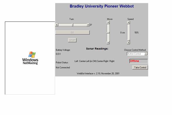
User Interface:
The user interface will be a Java applet. This applet will implement listeners to allow control of the robot with the user’s keyboard. There may be a map of the environment with an indicator of the robots position and heading updated periodically. This interface will also allow the user to adjust the speed of the robot. Video feedback will be provided by NetMeeting. An overhead camera may also be used to help the user navigate without running into obstacles. The existing java applet is shown in figure 1 below. This project will be an enhancement of this user interface
Figure 1
Demonstration
The only foreseeable way to test and confirm the success of this project will be to observe the robot and see that when battery voltage is low it returns to the dock. By hooking up a power supply instead of a battery one may be able to simulate a drained battery condition. The user interface will be demonstrated by normal use of the robot over the internet.
Standards and Patents
This Project will employ the 802.11b standard for Wireless LAN’s. This is a standard set forth by the IEEE. Compliance with this standard is insured by the use of a compliant 802.11b network card and 802.11b Wireless access point. This standard allows 11Mbit data transfer from a portable computer to the access point and then to a standard cable based LAN. I have been unable to find any patents dealing specifically with mapping and navigating a robot such as this in an environment such as ours
Also used for this project is the NetMeeting standard, known as H.323. This is a standard for negotiating methods of data transfer used in many teleconferencing situations. This should make it possible for anyone with an H.323 application to view the video stream from robot.
Equipment List
|
Item Description |
When Needed |
Price |
|
Casters and various other parts for the modification of Robot to mate with docking station. |
~April |
~$20-$30 |
|
Printed Circuit board for base of robot docking station |
~April |
TBD |
|
At least one set of new batteries for Robot |
Anytime |
~$30 |