In the last ten years, the National Science Foundation's
control theory directors and advisory committee members have encouraged
exploration of new control methods for complex industry applications. This
has been evident in NSF sponsored workshops and textbooks [1,2]. Artificial
neural network, fuzzy logic, and neural-fuzzy controllers have been the
emphasis and have received the most funding. Although these methods have
been used for many non-control applications, they have not been applied
widely in industry to nonlinear control applications. Also, these new methods
have not been compared sufficiently to other classical adaptive and non-adaptive
approaches.
The hydraulic systems area will be one of the more challenging areas for adaptive control especially in the large machinery area. The predominant method used in industry is human control. Many product parameters cannot even be specified because they rely on the persons experience and training. Automatic adaptive electronic controllers can eliminate the repetitive tasks performed by the human controllers as well as achieving better performance such as final position accuracy. Final positioning accuracy has only become a concern in the last several years. Good accuracy is difficult to obtain with conventional controllers. Autonomous (remote-controlled) vehicles used in mining and hazardous environments have been one area where control and product specifications are critical.
The first step to improve the hydraulic system is to add a conventional closed-loop electronic controller. The PID controller is the most widely used controller in industry and also the easiest method to design and implement. However, there are many problems and challenges with the PID controller for the large machinery hydraulic applications. The nonlinear time-varying parameters of the hydraulic system present a challenge for this control design method. Faculty research and a MSEE Thesis were recently completed regarding conventional PID controller design for a Caterpillar wheel loader, which is hydraulically controlled [3-6]. One product specification (speed) could not be met with the PID controller design. The primary limitation of the PID controller is that it is not adaptive to the different load conditions found in the large hydraulic system area. For example, the wheel loaders bucket load can vary from 0 to 33,000 pounds. An adaptive controller method can make the hydraulic system insensitive to varying load conditions. Experienced human operators can also perform this task but the electronic equivalent can provide better positioning accuracy and eliminate monotonous repetitive tasks from the operator.
In these hydraulic applications the cylinders can be several meters in length and are intended for efficient transmission of power and amplification of force. The cost of hydraulic systems used in large machinery can be on the order of hundreds of thousands of dollars. Control testing is normally performed on much smaller platforms such as robot arms, which can be designed to exhibit dynamics similar to larger hydraulic systems. Small robot arm systems can be purchased for approximately $6,000 for control algorithm testing. The robot arm system being used in our laboratory is very similar to the dynamics of the Caterpillar wheel loader. The mass, length, and type of robot arm were constructed by Dr. Dempsey to match the hydraulic dynamics. Five projects have been supervised with the robot arm systems provided by 1994 and 1999 Bradley Research Awards. Each robot arm assembly requires little laboratory space. The existing system requires a laboratory bench space of approximately six feet by two feet. The weight of the system is about twenty pounds.
The goal for this senior project is to design and develop C code for a small robot arm assembly controller using an enhanced 8051 microcontroller (80535). During the 1999/2000 school year, Megan Bern and Ritesh Patel designed and constructed an A/D and D/A converter interface board for the microcontroller board. This interface converts unipolar signals to bipolar signals for use in this system.
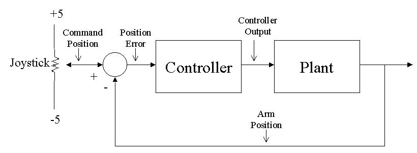
Various control systems will be utilized in an attempt to increase the speed and accuracy of the robot arm without excessive overshoot. Safety features such as motor current limit protection, and motor disable software for excessive position displacements will also be added. The add-on keypad and LCD (Liquid Crystal Display) will be used to provide a user-friendly interface for controller entry and status information. The user interface of the LCD shall consist of a menu from which the user may select either the command mode or the signal display mode. If the command mode is selected, options such as controller type, command position, command velocity, where the command signal is coming from, or a maximum position setting can be displayed and entered by the user. When signal display mode is selected, either the arm signal, the command position, the error signal, or control signals may be displayed. These signals are defined in Figure 1. The inputs and outputs of the system are listed below.
INPUTS:
OUTPUTS:
A/D Channels
D/A Channels
-Arm Position
-Controller Output
-Joystick Position
-Error Signal
-Motor Current
-Command Signal
-Feed-forward Signal
-PID-type Controller Signal
-Filtered Position Signal
Port Output Kill Relay
Keypad
LCD Display
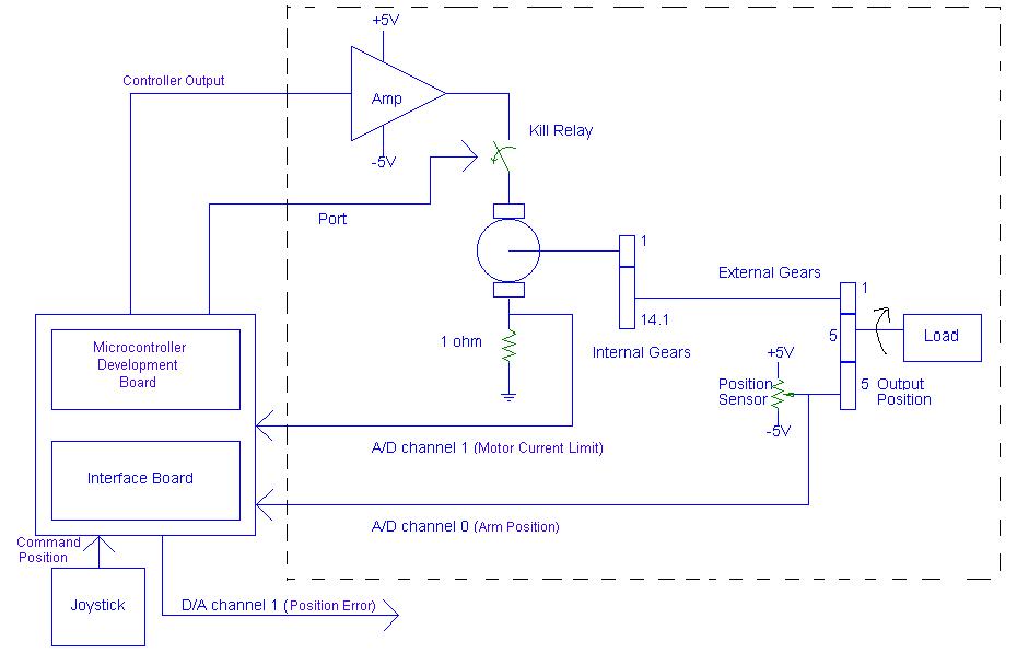
A high-level block diagram is shown in Figure 2. It includes the microcontroller development board, the DC motor assembly, some external gears, and a position sensor. The development board consists of a keypad, a LCD display, A/D and D/A converters, and the 80535 microcontroller. The microcontroller provides 24 bits of digital I/O, 4 counters/timers, and 10 external interrupts. The microcontroller board is manufactured by EMAC Inc., which is located in Carbondale, IL.
The D/A converter output drives the external power amplifier, which is connected in a voltage-follower configuration. The amplifier can supply a maximum of 3 Amps to a DC motor. The DC motor converts the control voltage to a mechanical position and velocity. The external gears provide a 70.5 reduction in rotor velocity for the external robot arm load. This arrangement is beneficial because the motor sees a small load; i.e., the gears step-up torque.
A potentiometer is used for the position sensor.
The pot arm is connected to the robot arm via a 1:1 gear. A voltage
supply of +/- 5 volts is used for the pot so that the arm position of zero
degrees corresponds to zero volts. The power amplifier, DC motor,
gear train, and potentiometer are part of a system manufactured by Quanser
Consulting. The company also provides test software and simple controller
software for their system.
Figure 1: Control System Block Diagram
Figure 2: High-Level Block Diagram:
PLANT
[1] Handbook of Intelligent Control- Neural, Fuzzy, and Adaptive
Approaches, editors D. White and D. Sofge, Van Nostrand Reinhold, New York,
N.Y., 1992.
[2] Neural Networks for Control, editors W. Miller, R. Sutton, P. Werbos, The MIT Press, Cambridge, MA, 1991.
[3] G. L. Dempsey. "ALS 990 Wheel Loader: Controller Design for Bucket and Steering Systems," Technical Report, Caterpillar Inc., Systems and Controls Research Department, November 1996.
[4] J. S. Alig, Investigation of Conventional and Neural Control Methods for Nonlinear Plants, MSEE Thesis, advisor G. L. Dempsey, December 1997.
[5] J. S. Alig and G. L. Dempsey. "Investigation of Anti-windup Control Compensation", Technical Report, Caterpillar Inc., Systems and Controls Research Department, August 1997.
[6] J. S. Alig and G. L. Dempsey. "Investigation of Feed-forward Compensation
Methods", Technical Report, Caterpillar Inc., Systems and Controls Research
Department, August 1997.