System Block Diagram


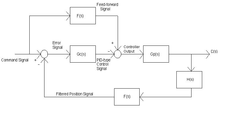
The following signals will be available on the D/A converter output channels.  The expanded control block
diagram is shown in Figure 1.

    Command position                -  Desired robot arm position from joystick or keypad input.

    Feed-forward signal              -  The output signal from the feed-forward compensator.

    Error signal                           -  The difference between the command signal and the filtered position signal.

    PID-type controller signal      -  The output signal from the PID(proportional+integral+derivative)-type
                                                      controller.

    Controller Output                  -  Signal that drives the robot arm system, connected to power amplifier.

    Filtered position signal            - The filtered actual position sensor signal.
 
    Sensor H(s)                           - H(s) = 0.028 volts/degree

    Filter F(s)                              - Low pass digital filter.

    Plant Gp                                - Gp = (29.8e^-0.02s)/( ( s/3.6 + 1 ) (s/3.6 + 1 ))
                                                      Dead-zone due to static friction was modeled as 20 ms time delay.  Note
                                                      that this is a type 0 system.
 

Figure 1:  Expanded Control System Block Diagram

    The software flowchart is shown in Figure 2.  The software contains an interrupt service routine as well as the main program.  The software will kill the motor if there is excessive position displacement or if the current exceeds its limit.  The software also checks to see if the joystick is present.  Timer 2 of the 80535 microcontroller will be used to generate the interrupt for the PID controller calculations.  Initially, the timer will be set for a 5 millisecond interrupt (200 Hz sampling). This fast sampling time will make the overall system look like a continuous-time system instead of a discrete-time system.  Later, the interrupt time will be decreased, but this subject will not covered until the second semester senior year (EE432 Control Theory II).  Dr. Dempsey suggested 200 Hz sampling based on previous research.  Since type 0 systems have constant error for step inputs, a PID controller is used.  A PID controller, when implemented with the plant, leaves the GcGp system as a type 1 system.  The steady state error for a type 1 system is equal to zero for step inputs.  Feed-forward control is utilized to create a fast transient response region in an attempt to speed up the total system.  Ideally, a perfect tracking system is desired, thus F = 1/Gp.

Figure 2:  Software Flow Chart

BACK TO HOME