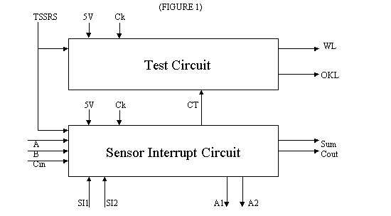
The various inputs, outputs, and their function on the system are described below. There are two entirely separate parts to our circuit.
1.) The sensor interrupt circuit mimics the microprocessor interrupt process. This circuit does a normal task when not interrupted, such as performing a multi-input / multi-output Boolean function. If an input sensor is activated, then the circuit stops its normal task and generates an alarm. A reset switch shuts off the alarm, and the circuit continues its normal task.
2.) The test circuit checks the sensor interrupt circuit for errors. This circuit will generate an additional interrupt that will override all other interrupts and functions of the sensor interrupt circuit. It is important NOT to confuse the sensor interrupts with the test circuit interrupt! The test circuit, once activated by a user, sequentially checks every stage of the circuit for errors and outputs a warning if there is a fault in the sensor interrupt circuit. It generates all possible inputs for the Boolean function, checking every stage (at the gate-to-gate level) for "stuck-at-one" and "stuck-at-zero" faults. If the test circuit finds an error before completing its entire check, it stops the test and outputs a warning light. If the test circuit completes the check and finds no errors, it outputs an OK light. The same reset switch deactivates the test circuit, and the circuit (that was just tested) continues its normal task.
Inputs
a. Sensor Interrupt Circuit
b. Test Circuit
Outputs
a. Sensor Interrupt Circuit
b. Test Circuit
*Exact number unknown at this time.