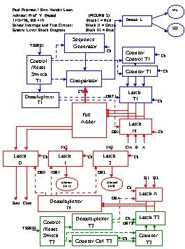
Sensor Interrupt CircuitControl Switch T1 (TSS1) enters Decoder T1 so that Latch N, the latch for normal Boolean operation, is selected. Inputs A, B, C, and D enter a series of AND-OR or NAND-NAND Combinational Logic gates. If sensor interrupts SI1 and SI2 are both off, then Decoder N selects Latch 0 and the outputs W, X, Y, and Z pass through Latch 0.
Control Switch T2 (TSS2) enters Decoder T2 so that Latch A, the latch for normal sensor / alarm operation, is selected. If sensor SI1 turns on, Decoder N selects Latch 1, and 5V passes through, activating Alarm A1. If sensor SI2 turns on, Decoder N selects Latch 2, and 5V passes through, activating Alarm A2. [One can think of the alarms as "burgler alarms" that go off as a sensor is tripped.] By manually switching off SI1 or SI2, the alarms reset (shut off) and normal Boolean operation resumes through Latch 0.
Clocks (Ck) enter the LATCH ENABLE pins to allow a continuous flow of output (WXYZ) from the input (ABCD). Selecting the latches by the OUTPUT ENABLE (OE0, OE1, OE2, OET1, OEN, OET2, OEA) means that the latch outputs are always off whenever they are not selected, regardless of the inputs to the unselected latches.
Control Switch T1 enters Decoder T1 so that Latch T1, the latch for Boolean operation testing, is selected. Note that Latch N shuts off and the Combinational Logic takes no more inputs from A, B, C, or D.
Control Switch T1 also selects Counter Control T1, which drives Counter T1. Counter T1 generates all possible input (ABCD) values in sequence, which pass through Latch T1 and into the Logic. Counting occurs continuously.
Thirdly, Switch T1 activates the Comparator and starts up the Sequence Generator. The sequence generator is a long series of registers (memory) that contain the "truth table" of output values not only for W, X, Y, and Z, but also for inter-stage outputs between the logic gates inside the Logic block. Each clock cycle (Ck) the Sequence Generator moves a truth table value into one side of the Comparator. On the other side, actual output values (W,X,Y,Z, and inter-stage) are picked up by the Circuit Tester (CT; the red arrow) and compared with the correct output values from the Sequence Generator.
The result of the comparison enters Decoder L. If the actual output value equals the correct value in the sequence, the OK Light (OKL) activates. If the actual output value does not equal the correct value in the sequence, the Warning Light (WL) activates.
Control Switch T2 enters Decoder T2 so that Latch T2, the latch for alarm testing, is selected. Note that Latch A shuts off and the sensor interrupts (SI1, SI2) have no effect on Alarms A1 and A2.
Control Switch T2 also selects Counter Control T2, which drives Counter T2. Counter T2 continuously selects Latches 1 and 2 (via. Decoder N) to test if the alarms are working. (Latch 0 is also momentarily selected, but its outputs are meaningless; Latch N is off.
Once the testing is complete, three things must occur: Switch T1 must be toggled to select Latch N, Switch T2 must be toggled to select Latch A, and the Reset Switch (RS) must be toggled to reset the counters.