Project Datasheet

Project:  Alternative Energy System
Team:  Jeremy Tresenriter and Jim Williamson
Advisor:  Mr. Steve Gutschlag

System Maximum Values

Wind Generator

 
Rated Voltage Vrated (Vmax) 50V
Rated Current Irated (Imax) 2A
Rated Power Prated (Pmax) 100W


Solar Cell or Solar Cell Array

 
Maximum Voltage (open circuit) Vmax  ( Voc) 42.0V
Maximum Current (short circuit) Imax ( Isc) 3.25A
Rated Voltage Vrated 34.0V
Rated Current Irated 2.95A
Rated Power Prated 100W


Battery Array

 
Maximum Charging Voltage (at no load) Vmax  60V
Mininum Voltage (loaded) Vmin 44V
Maximum Charging Current (at no load) Imax 2.5A
Minimum Charging Current (loaded) Imin 1.5A1
Maximum Output Voltage  Vmax 48V
Maximum Output Current Imax 1.56A
Maximum Power Pmax 75W


Load

 
Maximum Voltage Vmax 50V
Maximum Current Imax 1A
Maximum Power Pmax 50W


Microprocessor

Extracted from Motorola 68HC11 E Series Manual (Appendix A, page 1) 
 
Rating
Symbol
Value
Unit
Supply Voltage
VDD
–0.3 to + 7.0 
V
Input Voltage 
Vin
–0.3 to + 7.0
V
Operating Temperature Range 
      MC68HC(7)11Ex 
      MC68HC(7)11ExC 
      MC68HC(7)11ExV 
      MC68HC(7)11ExM1. Dependent upon energy available from sources 
      MC68HC811E2 
      MC68HC811E2C 
      MC68HC811E2V 
      MC68HC811E2M 
      MC68L11Ex
TA


T L to T H
0 to + 70
–40 to + 85
–40 to + 105
–40 to + 125
0 to + 70
–40 to + 85
–40 to + 105
–40 to + 125
–20 to + 70


°C


Storage Temperature Range
Tstg 
–55 to + 150
°C
Current Drain per Pin 2 
   Excluding VDD , VSS ,  AVDD, 
            VRH , and VRL
ID


25 


mA


NOTES: 
    1. Dependent on energy available from sources 
    2. One pin at a time, observing maximum power dissipation limits 


User Interface

Description: 

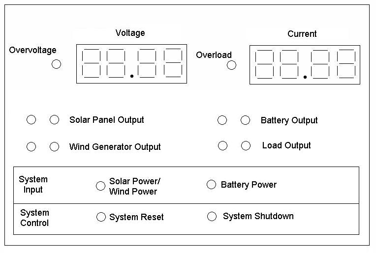
    The user interface (Fig. 1) contains a mixture of displays and controls which will allow the user to monitor and operate the system.  The display system will include 2 liquid crystal displays (LCDs) and 8 light Emitting Diodes (LEDs).  One LCD will give the reading for the voltage of the selected output and the other will give the current for the same selected output..  One LED will operate in conjuction with each LCD to indicate if the reading being displayed is over the maximum limit.  These LCD-LED combinations will allow the user to monitor each of the following subsystems: solar power, wind power, battery power, and load consumption.  Four of the remaining six LEDs are used to indicate which reading is being shown.  One LED is placed adjacent to each of the four listed outputs that are to be monitored. Only one output will be capable of being monitored at any one time and the corresponding LED for that output will be lit as long as that quantity is displayed. The two remaining LEDs at the bottom of the interface indicate to the user if the system is running on solar and wind power or battery power. 

    The control mechanisms for this system are six push buttons.  The first push button is a system reset, its function is to allow the user to reset the system in the event that the system shuts down due to a overvoltage or overcurrent situation.  The second push button is a so called panic button which allows the operator to shut down the system manually in the event that the system does not go into automatic shut down as a result of overvoltage or overcurrent in the system. The last four push buttons sit adjacent to the LEDs for each of the outputs.  Depressing the push button will change the display readings to the appropriate voltage and current readings for that selected output. 


 Fig. 1 View of User Interface


Testing Procedures

    Testing procedures for this system will be implemented by using numerous voltmeters and ammeters.  The testing procedures include monitoring the various currents and voltages within the system and comparing them to the predetermined values given within the specification sheets.