
Senior Project: Functional Description
|
Functional Description |
Summary
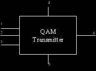
This project involves the design, building and testing of a transmitter and receiver utilizing Quadrature Amplitude Modulation (QAM). QAM allows data to be sent at relatively high speeds in situations where data must be sent in a narrow bandwidth channel, such as a coaxial-based network or a mobile paging network. A QAM transmitter is a multilevel modulated bandpass signal generator that two binary inputs at a time by using amplitude and phase of a mixed sine and cosine carrier to allow much more information to be transmitted in a limited bandwidth. Generally, QAM is designated by the number of symbols generated, such as 16-QAM. This indicates the number of levels that the multilevel output signal has. The general modulated QAM signal is as follows:
s(t) = x(t) cos w ct y(t) sin w ct
where x(t) and y(t) are the two input signals. In 16-QAM, the two signals transmit 4 level multilevel signals. This project will use at least a 16-QAM design. Typically, x(t) and y(t) are generated by a baseband processor which splits a single input signal into two signals. The final design may or may not include this processor to demonstrate the ability to send two distinct signals.
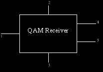
Finally, the receiver then uses a PLL
(Phase Locked Loop) to synchronize itself to the transmitted signal to
separate the sine and cosine waves and correctly decode the transmitted
signal.
|
|
| Transmitter:
|
Receiver:
|