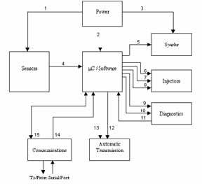
Power:
This subsystem contains all circuitry
that will regulate power to the microprocessor, sensors, and sparks subsystems.
This would include such circuits as voltage regulators, converters, line
conditioners, and oscillators.
Sensors:
This subsystem contains the physical
sensors and the interfacing to the microprocessor. Any analog to
digital converters, filters, and scaling circuitry would be contained in
this system.
uC / Software:
This subsystem contains the microprocessor,
address decoding circuitry, and program EPROM. The EPROM will contain
the code for the controller, in which a full program flow chart is shown
in Fig I. This subsystem can be looked upon as the brains of the
operation, because all the inputs and outputs will be maintained from here.
Manipulating the control outputs based on the inputs received from the
sensor subsystem attains the control of the engine.
Sparks:
The spark subsystem contains the
ignition coils. It accepts a timing input from the microprocessor
and fires the spark plugs accordingly.
Injectors:
In this subsystem, the injectors,
fuel pump, and timing/sequence circuitry are contained. The function
of the system is to control the injector sequence and duration of fuel
spray into the pre-combustion chamber. During startup, the fuel relay
pump is turned on prior to starting the engine so that the fuel line is
pressurized. This allows pre-prime of the engine prior to startup.
Diagnostics:
This subsystem is responsible to
maintain the reliability and working condition of the controller.
Two inputs, power and error detection, allow the driver to provide the
controller with immediate attention. This system also maintains the
trouble shooting routine that tests the controller to ensure working condition,
and if not, return the error code corresponding to the detected problem.
Automatic Transmission:
This system contains two power
transistors that will be used to control the up and down sequence of the
transmission. Two inputs from the microprocessor will determine when
the transmission is to shift.
Communications:
This subsystem will maintain the
link between the controller and the outside world. A serial communication
port will be used to establish a link to a PC for reading of diagnostic
codes and real-time calculations. The EPROM look-up table is also
contained in this subsystem because it can be exchanged to incorporate
other desired engine characteristic.
Key to Labels:
1) Power to
Sensor Subsystem
2) Power to
Microprocessor
3) Power to
Spark Ignition System
4) Sensor Inputs
to Microprocessor
5) Timing for
Sparks
6) Fuel Relay
Control Signal
7) Injection
timing Signal
8) Revolution
Limiting Signal
9) Power Detect
Signal
10) Error Detect
Signal
11) Diagnostic
Start Input
12) Transmission
Shift Up
13) Transmission
Shift Down
14) Lookup Table
Signal
15) Serial Port
Communication