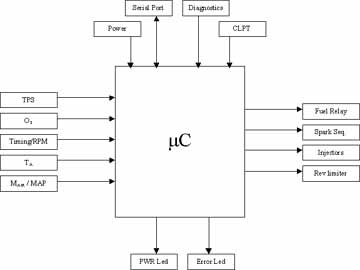
TPS (Throttle Position Sensor) Inputs the angle of the throttle pedal (or accelerator).
MAP
(Manifold Absolute Pressure) Senses the pressure of the manifold
where the intake air is pressurized before being mixed with fuel
and injected into the engine.
MAIR (Mass Flow Rate of Air) Senses the amount of air being pushed into the engine so that the proper fuel can be mixed with it.
Oxygen (O2)
A feedback input that measures the amount of oxygen in the exhaust.
The amount of oxygen in the exhaust is an indicator of
how much fuel is being used and allows for self-tuning of the engine.
Timing/RPM
Inputs the speed of the engine and is the basis for all of the spark
and injection timing calculations.
TA
Senses the temperature of the air prior to entering the engine.
Power 12Vdc 30A max power from the engine. This will be used in the power supply for the controller.
Diagnostic An input pin that performs a self-test of controller and sensors.
CLPT (Curve
Look Up Table) EPROM chip which contains information on computing
fuel injection and spark timings for a desired
characteristic curves of the engine. This will be external
to the controller so that they may be interchanged
for desired operation of the
motor. (I.e. Economy, Race, etc.)
OUTPUTS/INTERFACE
Serial Port
Bi-directional communications to interface with PC for evaluation of
error codes from diagnostics. Also provides real time view
of calculations and control signals.
Fuel Relay Controls fuel pump by turning it on before the engine starts, and then shutting it down after the engine stops.
Spark Sequence Four control signals that fire the spark plugs.
Injectors Four control pins that fire the injectors when the valves open to let the fuel into the cylinder.
Rev Limiter
Controls a relay switch that cuts the signal to the ignition when the
RPMs of the engine become to high. This is to prevent
redlining of the engine and possible damage.
PWR LED An LED that activates when the controller has power.
Error LED An LED that activates when the controller has detected an error.